


Maintenance
4–16
760A / 760D / 760N
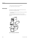
b. Remove the four screws from the rear.
c. The board may now be separated from the front panel and the compo-
nents should be accessible.
5. To reassemble, reverse the procedure.
NOTE. When remounting the Front Panel board to the front panel, carefully line
up the LED bars so they fit inside the cut–outs in the front panel.
1. Disassemble the front–panel assembly using the procedure just given, and
remove the LED bar.
2. Install the new LED bar so the end with the three leads closely spaced are at
the top of the LED bar socket. The LED bar will not work properly if
installed backwards.
3. To replace a damaged socket, unsolder the old socket. Notice that there are
two sockets for each LED bar.
4. Replace the socket with two 20–pin sockets, trimming three pins from either
one to provide the 37 pins necessary for the LED bar.
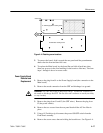
1. Remove the following connections: P110 and P135 (to Front Panel board),
P153 (to Power Supply board), P419, trace rotation (to CRT), P862 (to H
defl. amp) and P882 (to V defl. amp).
2. Push the trace rotation lead through its hole in the Main board.
3. Remove the knobs from the GRATICULE and ILLUMINATION controls.
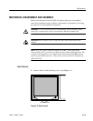
4. Remove the eight retaining screws. See Figure 4–4 for locations.
LED Bar and Socket
Removal and
Replacement
Main Board Removal and
Replacement