


Installation
760A / 760D / 760N
3–3
graticule supplied with the instrument. Detailed instructions for removing the
bezel can be found under the Mechanical Assembly/Disassembly topic in
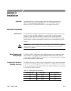
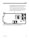
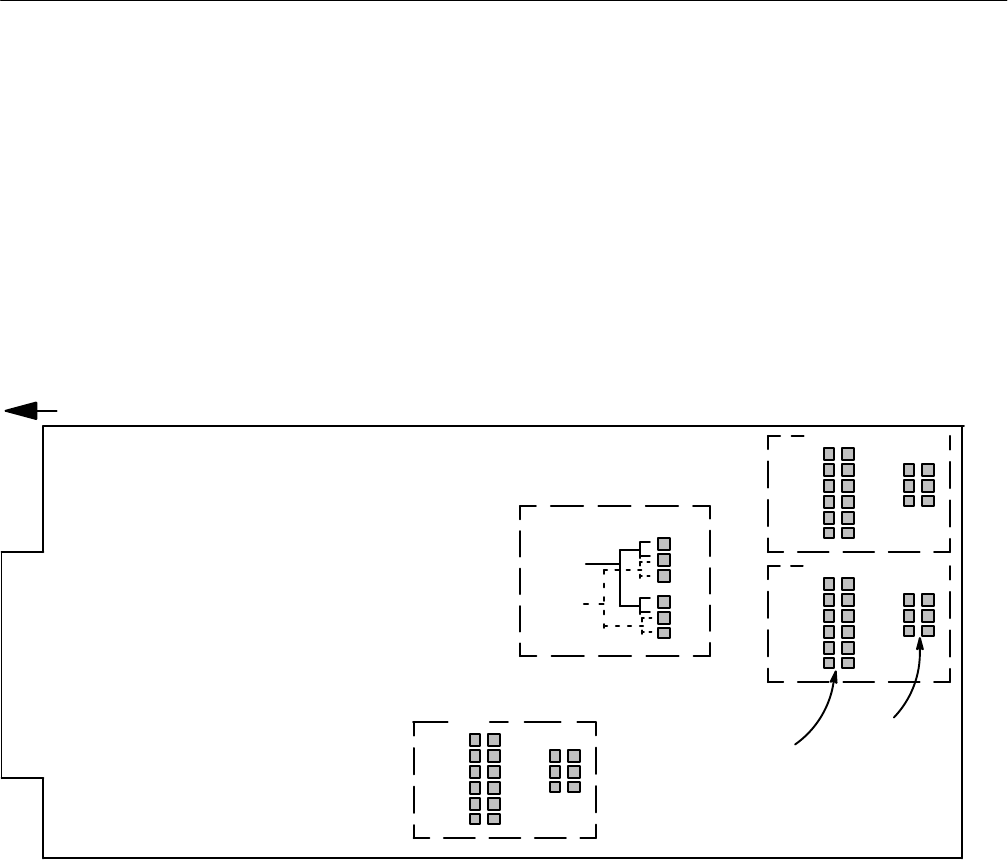
SECTION 4, MAINTENANCE. Then move two jumpers on the Main circuit board,
J273 and J373, to the position labeled X–Y (pins 2 & 3) in Figure 3–1.
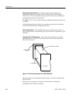
Also for X–Y display orientation, rotate P886 (on back of A3, Main board) so
pins 1 and 2 of the connector mate with pins 2 and 1 of J886 (connect back-
ward). Repeat with P862/J862. Remember to return P886 and P862 to their
normal (pin 1 to pin 1) positions for Sound Stage display orientation. This
provides correct phasing for both display orientations.
INPUT
TERMINATION
JUMPERS
RIGHT INPUT
FRONT
ASSEMBLY A3
MAIN BOARD
TOP
J385
J392
L+R
L
R–L
–R
SOUND
STAGE
X–Y
J273
J373
DISPLAY ORIENTATION
J185
AUXILIARY INPUT
J657
U
0 dB
4 dB
8 dB
12 dB
16 dB
INF
600
150
J664
INPUT
SENSITIVITY
JUMPERS
LEFT INPUT
J192
INF
600
150
INF
600
150
U
0 dB
4 dB
8 dB
12 dB
16 dB
U
0 dB
4 dB
8 dB
12 dB
16 dB
Figure 3–1: 760A / 760D / 760N jumper locations for input and display orientation selections