


760A / 760D / 760N
6–1
Section 6
Theory of Operation
INTRODUCTION
This section is intended to give a thorough understanding of the 760A / 760D /
760N Stereo Audio Monitor’s operational theory. A block diagram is provided
to show the relationships between major functional blocks of circuitry. Each
block directly relates to a portion of circuitry on a schematic that is described in
detail in this section.
The name of each schematic diagram is listed as a paragraph title (upper case)
and is followed by the diagram number (in parenthesis). The circuit blocks on
each diagram follow the appropriate diagram title. When identical circuits exist
for vertical and horizontal, or for left or right channels, only one will be
described.
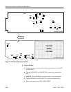
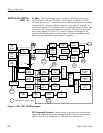
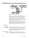
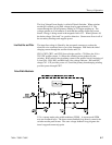
BLOCK DIAGRAM
Figure 6–1 (on the following page) is the 760A / 760D / 760N block diagram.
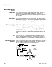
DETAILED CIRCUIT DESCRIPTIONS
The LEFT, RIGHT, and AUX input amplifiers are instrumentation amplifier
circuits. For the standard 760A/760D/760N, the gain (in dB) may be selected by
moving J185, J385, or J657 for the LEFT, RIGHT, or AUX, respectively, to the
appropriate pins for reference levels of 0, +4, +8, +12, or +16 dBu. There is an
additional position, U, which is provided for installations which use a reference
level other than these. See SECTION 3, INSTALLATION, for instructions on
calculating the proper resistor values.
The 760D and the 760N are designed to indicate 0 dB and +6 dB, respectively,
with a 1.55 V
rms
input.
This is in accordance with DIN 45 406 and, for the 760N, Technical Recommen-
dation N9. In order to accomplish this, resistors of the appropriate value have
been installed in the positions selected by the U settings of J185, J385, and J657;
therefore, only the U positions may be used for the 760D and 760N.
The inputs may be terminated by 150 Ω, 600 Ω, or >20k Ω as selected by J192,
J392 and J664 for LEFT, RIGHT and AUX, respectively.
INPUT AMPLIFIERS <1>