


Maintenance
4–10
760A / 760D / 760N
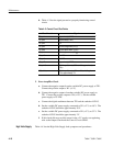
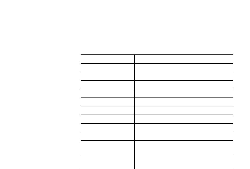
b. Table 4–3 lists the signal present in a properly functioning control
circuit.
Table 4–3: Control Circuit Test Points
Circuit Location Signal
U5, pin 1 Approximately 5 VDC
U5, pin 2 Approximately 2 VDC
U5, pin 3 0 V
U5, pin 4 80 kHz triangle wave, 2 V
p-p
U5, pin 6 80 kHz square wave, 18 V
p-p
U3, pin 1 80 kHz square wave, 5 V
p-p
U3, pin 2 2.1 VDC
U3, pin 6 2.9 VDC
U3, pin 7 Approximately 5 VDC
U4, pin 13 80 kHz repetition rate, 300 ns width, approximately
3 V
p-p
Q8, collector 80 kHz repetition rate, 400 ns width, switching from
5 V to approximately 2 V
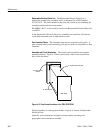
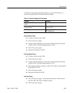
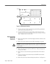
5. Error Amplifier Check
a. Connect the negative output from the variable DC power supply to TP1.
Connect the positive output to W1 (+5 V).
b. Connect the negative output of another variable DC power supply to
TP1. Connect the positive output to W4 (+15 V). Set the variable
power supply to 20 VDC.
c. Connect the digital multimeter between TP1 and the cathode of CR15.
d. Set the variable DC power supply connected to W1 (+5 V) to 4.8 V. The
cathode of CR15 should be approximately 20 V.
e. Set the variable DC power supply connected to W1 (+5 V) to 5.2 V. The
cathode of CR15 should be approximately 2 V.
f. If this check did not reveal the cause for the +5 V supply not regulating,
refer to the Output Check and the Control Circuit Check.
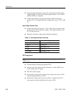
Table 4–4 lists the High Volts Supply fault symptoms and procedures.
High Volts Supply