


Maintenance
760A / 760D / 760N
4–3
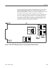
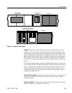
CIRCUIT BOARD
ILLUSTRATIONS
PARTS LOCATING
CHART
SCHEMATIC
THEORY OF OPERATION OR
ADJUSTMENT PROCEDURE
SCHEMATIC
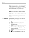
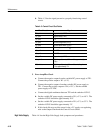
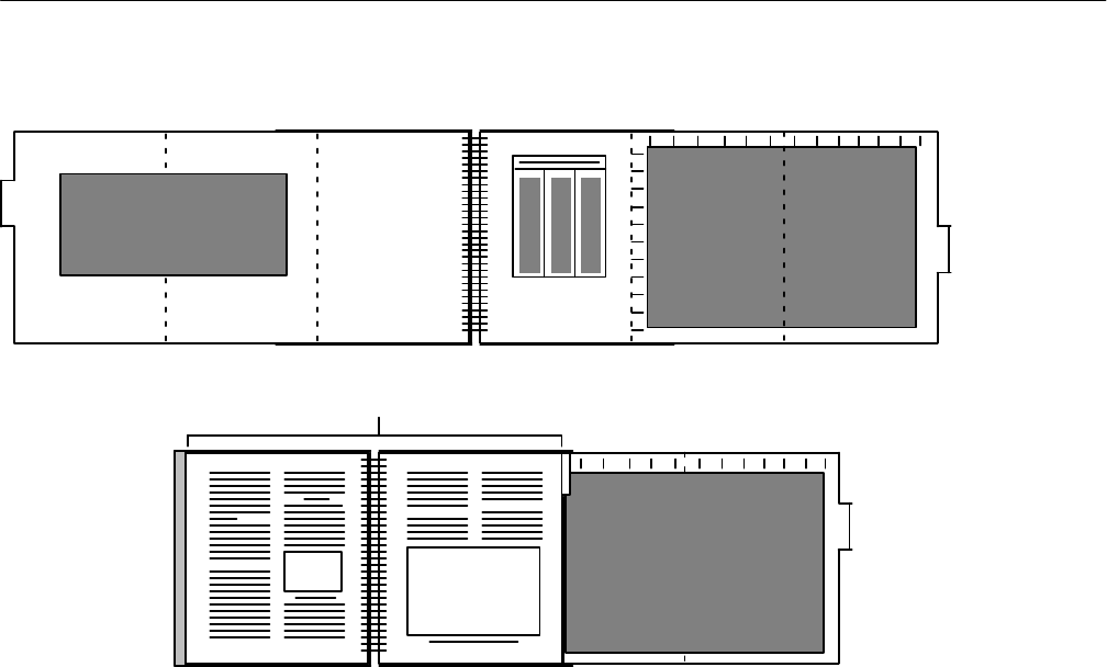
Figure 4–1: Using the foldout pages
Diagrams. Block and circuit diagrams are the most often used aids to trouble-
shooting. The circuit number and electrical value of each component is shown
on the diagram (see the first page in the Diagrams section for a definition of the
reference symbology used to identify components in each circuit.) Refer to the
Replaceable Electrical Parts List for a complete description of each component.
Those portions of the circuits that are mounted on circuit boards or assemblies
are enclosed in a gray border, with the name and assembly number shown on the
border.
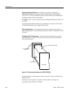
Circuit board input and output signals are applied through multi–pin connectors.
The connector holder has numbers that identify terminal connectors numbered 2
and up. A triangular key symbol on the connector is also located on the circuit
board to identify pin 1 so that the connector can be properly oriented. A pin
replacement kit including necessary tools, instructions, and replacement pins is
available from Tektronix, Inc.
Circuit Board Illustrations. Electrical components, connectors, and test points are
identified on circuit board illustrations located on the back of the preceding
schematic diagram.
Theory of Operation. These pages can be turned to and read while the schematic
diagram for that circuit description is folded out.