


Performance Check and Calibration Procedures
760A / 760D / 760N
5–7
d. Move the leveled audio signal generator output from the RIGHT to the
LEFT AUDIO INPUT and repeat part c of this step.
10. MANual Gain, CAL Gain and PEAK HOLD
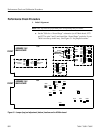
a. Connect the leveled audio signal generator output to the LEFT and
RIGHT AUDIO INPUTs.
b. CHECK – that when the DISPLAY GAIN is varied in its MANual gain
range (between detents), the CRT display size varies with no rotation of
the trace.
c. Set the DISPLAY GAIN control to CAL and remove the signal from the
RIGHT AUDIO INPUT.
d. CHECK – that the trace extends to the major amplitude mark on the L
graticule line.
e. Connect inputs to all three AUDIO INPUTs.
f. CHECK – that when the audio inputs are removed from the 760A, two
segments at the top of the indicated levels remain lit for approximately
three seconds.
11. Check Z–Axis Dimming
a. Connect the leveled audio signal generator output to the RIGHT AUDIO
INPUT and set the DISPLAY GAIN control to MANual.
b. CHECK – that when the input signal is removed, the display disappears.
12. Check Bar Frequency Response
a. Connect the leveled audio signal generator outputs to the LEFT, RIGHT,
and AUXILIARY AUDIO INPUTs, and set SELECT to AUX.
b. With the EXPAND SCALE push button depressed, set the audio signal
generator output level so the LEFT bar indicates:
760A: –8 dB (TEST)
760D: –9 dB
760N: 0 dB (TEST)
c. CHECK – that when the audio signal generator frequency is varied from
20 Hz to 20 kHz and the EXPAND SCALE push button is depressed,
each bar amplitude changes less than 0.5 dB, which is:
760A: "5 bar segments
760D: "4 bar segments