


Theory of Operation
760A / 760D / 760N
6–5
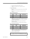
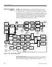
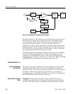
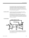
Peak Hold Circuit. The Peak Hold circuit is entirely digital. It stores peak values
as follows. On each scan of the bar (300 times per second) the Comparator
(described above) provides a CMP
signal to PAL U438. The PAL then asserts
BAR ENABLE
, which allows the Bar Anode Driver to operate. The PAL also
asserts DELAY to clock the counter state corresponding to the signal level into
the latch, U428. On succeeding bar scans digital comparator U432 compares the
latched number, at its Q inputs, with the counter state corresponding to the new
signal level, at its P inputs. If the new state exceeds the old, the comparator
signals the PAL through the GREATER
line, and the PAL responds by again
asserting DELAY, clocking the new peak value into the latch. Asserting DELAY
also clocks a retriggerable monostable circuit, U436, which has a three–second
period. If the monostable circuit reaches the end of this period without being
retriggered it raises the TIMEOUT line high, to signal the PAL that it is time to
cancel the peak. The PAL then asserts GATE
, clearing the latch. In this manner,
the latch keeps track of the counter state corresponding to the peak to be
indicated.
The circuit indicates peak values as follows. As the counter scans the bar, the
comparator monitors the counter and notifies the PAL, via the EQUALS line,
when the counter state matches the stored peak. The PAL then turns on the bar
for two clock periods using the BAR ENABLE
line, lighting two successive bar
segments to indicate the value of the stored peak. If a stored peak persists for
three seconds without being exceeded, it is canceled by the monostable circuit.
If it is exceeded, the monostable circuit is retriggered to restart the time–out
cycle.
Peaks below –20 dB are prevented from being indicated by the PK BLK
line,
which is controlled by a data line from the scale–shaper ROM, U132 on diagram
(3).
A further description of the PAL signals for troubleshooting can be found in
SECTION 4, MAINTENANCE.
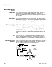
Since the LEDs comprising the bar are internally arranged in a 10–by–10 matrix,
they are addressed by two BCD–to–decimal decoders; one driving the anodes
and one driving the cathodes. U308 drives the anodes through buffers U208 and
U223A. The cathode decoder/driver, U320, is located on the front–panel board
(diagram 8). Gate U708 provides a way to turn the bar on and off by forcing the
decoder into a non–BCD state when the BAR ENABLE
line is high. This forces
all the decoder outputs high, and the LED anodes low.
The PEAK HOLD front–panel switch is debounced by an RC network and
Schmitt gate U825A & B, which toggles flip–flop U823 for on/off control.
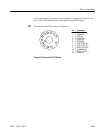
Bar Anode Driver (Left)
Peak Hold On/Off