


Theory of Operation
760A / 760D / 760N
6–3
Trace Rotation. A dc current through the trace rotation coil magnetically corrects
rotation.
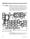
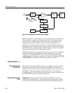
Gain Control Logic. The signal from the Input Amplifier is full wave rectified in
the precision rectifier, U462, and filtered and compared by U361 to determine
the largest signal. The comparator output is combined with AUTO and CAL in
U153, a one of eight decoder. Depending on the input combination, analog
switches U172 and U167 select the appropriate signal to be applied to the Gain
Control circuit. AUTO is the clockwise detent position of the front–panel
DISPLAY GAIN control, and CAL is the counterclockwise detent. The manual
gain control applies a variable dc voltage to the Gain Control circuit. In the
CAL detent, the voltage is set by an internal pot, R262. In the AUTO detent, the
control voltage is the larger of the Horizontal or Vertical signals as determined
by the comparator, U361.
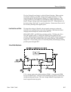
Gain Control (Vertical). U680 is a dual gain control circuit. This circuit rectifies a
control signal and buffers it to attack capacitor C586 and decay capacitor C581.
The dc level controls the transconductance of the DG block. In the gain control
circuit, the DG circuit is used to control the ac feedback of an op–amp such that
the output level stays constant for an input signal between about –20dB to
about +8 dB, for the standard 760A. This range changes to about –25 dB to
+5 dB for the 760D, and about –15 dB to +15 dB for the 760N. The attack and
decay capacitors allow for fast gain reduction on signal peaks, and for slow
recovery to keep low frequency signals from “pumping” the gain. The dc
feedback is provided by R593, R685 and C588. R686 corrects for dc offset,
allowing maximum output amplitude. R782 (offset adj) trims out pattern
“bounce” that would result from the control signal appearing at the output.
Low Pass Filter (Vertical). U894 is a four-pole low pass filter with a cutoff at
about 34 kHz. R789 is adjusted for phase match between the two channels.
Output Amplifier (Vertical). The output amplifier is a differential cascaded
amplifier with R601 (VERT POSITION) adjusted for centering, and R786
adjusted for gain.
Z–Axis Dimming. The Z–Axis circuit prevents CRT burn by turning off the CRT
when the larger of the horizontal or vertical signals fall below a minimum level.
The two signals are amplified, rectified, and filtered by U880, Q776, and C776.
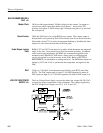
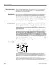
The level indicator is a broad term that refers to all the circuitry associated with
the LED bar graph. This circuitry is found on diagrams 2 and 3, and is based on
the principle illustrated in Figure 6–2.
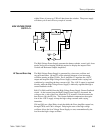
AGC & CRT DEFLECTION
AMPLIFIERS <5>
LEVEL INDICATORS