Maintenance
760A / 760D / 760N
4–11
Load the Low Volts Supply with the instrument, or with the 20 W resistor as
stated at the beginning of the Troubleshooting Procedure.
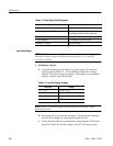
Table 4–4: High Volts Supply Fault Symptoms
Symptom Procedure
Unable to focus CRT using the front-panel
control
Focus Amplifier Check
Unable to adjust CRT intensity using the
front-panel control
Z-Axis Amplifier Check
Grid Drive Check
No CRT display High Voltage Oscillator Check
CRT Voltage Check
Focus Amplifier Check
H Unsolder and lift one end of R24.
H Turn on the power supply.
H Using the digital multimeter, measure the voltage between TP1 and the
collector of Q1. It should be approximately –140 V.
H Turn off the power supply.
H Reconnect the lifted end of R24.
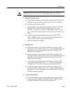
Z-Axis Amplifier Check
H Unsolder and lift one end of R8.
H Turn on the power supply.
H Using the digital multimeter, measure the voltage between TP1 and the
collector of Q4. It should be approximately +10 V.
H Short together the base and emitter of Q5. The collector of Q4 should be
approximately +100 V.
H Turn off the power supply.
H Reconnect the lifted end of R8.
Grid Drive Check
H Turn off the power supply. Use the digital multimeter’s diode check to
test CR1, CR2, CR3, CR5, and CR6 for shorts.
H Turn on the power supply.


