


Theory of Operation
6–4
760A / 760D / 760N
Comparator
Filter &
Rectifier
Decoder /
Driver
LED Bar
DAC
ROM Lookup
Table
CounterClock
DAC Ramp
Input
Signal
–
+
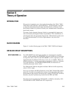
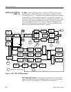
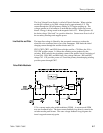
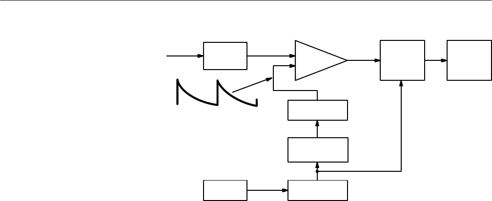
Figure 6–2: Simplified Level Indicator block diagram
The LED segments of a 100–segment bar are scanned from top to bottom about
300 times per second by a down–counter and decoder. The counter simulta-
neously addresses a ROM lookup table which contains the amplitudes repre-
sented by each segment of the bar. A DAC converts this succession of
amplitudes to an analog voltage ramp which is compared with the rectified and
filtered input signal. When the ramp voltage becomes less than the input signal,
the LED bar driver is enabled, lighting the LED segments. Hence, all segments
representing amplitudes less than the signal level are lit.
The ROM lookup table determines the shape and range of the scale. In addition
to the normal scale range, the ROM also contains the magnified scale range
actuated by the EXPAND SCALE button. Other scales for calibration and
troubleshooting are selected by a special service switch, S340. Refer to SECTION
4, MAINTENANCE, for information on the settings and uses of S340.
The signal from the Input Amplifier is full–wave rectified in precision rectifier
U445A & B, isolated by U445C & D, filtered with PPM time constants and
buffered by U453. The attack time constant is such that a 10 ms sine wave burst
will indicate 1 dB below true peak value. The fall time is 1.8 seconds for a
20 dB indicator drop. R347, R546 and R758 provide calibration adjustments for
the LEFT, RIGHT and AUX indicators, respectively.
Comparator. U635B compares the rectified signal with the DAC ramp and
provides the bar enabling signal. This signal is passed through logic contained
in a PAL, U438, which is part of the Peak Hold circuit description that follows.
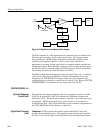
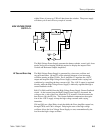
GRAPH DRIVERS <2>
Dynamic Response
Control (Left)
Signal Peak Processor
(Left)