


Maintenance
760A / 760D / 760N
4–15
2. Slip the CRT part way back into position and feed the trace rotation wires
(and plug) back through the hole in the Main board.
WARNING. The CRT may retain a dangerous charge. Ground the the anode
connector to discharge the CRT. Do not allow the conductor to touch your body
or any circuitry.
3. Use a screwdriver to ground the anode connector on the CRT to the chassis.
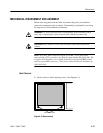
4. Slide the CRT into the instrument, guiding the rubber manchet on the end of
the shield into the rear CRT support.
5. Align the socket on the A10 CRT Socket board with the pins and key on the
CRT. Gently push the CRT and the socket board together until the CRT pins
are fully seated in the socket.
6. Replace the trace rotation connector (P419, Main board), and snap the anode
lead onto the anode connector on the side of the CRT.
7. Wipe the faceplate of the CRT to remove fingerprints, then replace the bezel.
If the fit is too tight to allow the bezel to go into position, or if the CRT has a
loose fit after the bezel is completely tightened down, then the rear CRT
support must be repositioned.
To reposition the rear CRT support, loosen the two nuts that hold the support
in place. With the CRT and bezel in place, push the support towards the
front of the instrument until it is snug against the rubber manchet on the rear
of the CRT shield. Tighten the two support nuts.
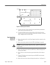
1. Remove the two Pozidrive screws from each rear–panel XLR connector.
2. Remove the five screws from the rear panel.
3. To replace, reverse the procedure.
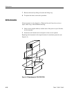
1. Remove multi–pin connectors P110 and P135 from the Main board.
2. Remove the two screws that hold the front–panel assembly in place.
3. The assembly can now be removed by slipping it through the front.
4. To access the Front Panel board components:
a. Remove the two knobs from the front.
Rear Panel Removal and
Replacement
Front Panel Assembly
Removal and
Replacement