


Maintenance
4–6
760A / 760D / 760N
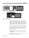
Position 3 a step function used to check DAC linearity and bit transition glitches.
The first nine addresses are one–bit steps. Single transitions are present until
one–quarter scale where three successive bits are used for position markers.
Since maximum glitch occurs at half scale, the MSB transition is exhibited three
times (the only times the scale goes down). The eight bits surrounding the MSB
transition are displayed. The upper addresses nearly mirror the lower 50.
Position 4 is all zeros which is maximum DAC output and is used to adjust gain.
Position 5 is all ones which is minimum DAC output and is used to set offset.
Position 6 is a linear scale with one–half LSB error on odd addresses and is used
to check system linearity with linear input.
Position 7 is the Expanded scale with 20 dB Offset that is used in the Perfor-
mance Check procedure to check bar accuracy with a 20 dB (18 dB for 760N)
input signal.
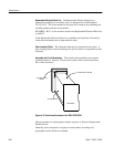
The following PAL signal specification details the operation of PALs U438,
U638, and U848 and may be helpful when troubleshooting the Peak Hold circuit.
PIN 1 CLOCK
from U825, approx. 30 kHz
PIN 2 CMP
goes low when measured signal is equal to or greater than DAC
ramp.
PIN 3 EQUALS
goes low when DAC ramp is equal to stored peak.
PIN 4 TIMEOUT goes low while the monostable circuit is timing the
three–second peak–hold delay.
PIN 5 PK BLK
(peak blank): a low level prevents peak segment from being
turned on. This line is controlled by a bit position in the scale–shaper
ROM, and is used to keep from displaying peaks below 20 dB.
PIN 6 PK ON
(peak on): a high level from the PEAK–ON flip–flop U823
turns on the PEAK–HOLD feature.
PIN 7 GREATER
goes low when DAC ramp is greater than the stored peak.
PIN 8 (not used)
PIN 12 GATE
goes low to reset the peak value latch after the three–second
timer has timed out.
PAL Signal Specification