


Theory of Operation
760A / 760D / 760N
6–9
within 50 ms of power up, U3B will shut down the switcher. The power supply
will then cycle on and off every couple of seconds.
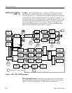
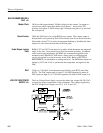
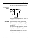
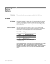
The High Voltage Power Supply generates the heater, cathode, control grid, focus
anode, and post accelerating potentials required to display the outputs of the
Vertical and Horizontal Output Amplifiers.
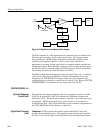
The High Voltage Power Supply is generated by a sine wave oscillator and
step-up transformer. Q6 and T1 are the principal elements of an Armstrong
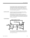
oscillator running at about 22 kHz. Error Amplifier U2 regulates the +100 V
output and keeps the High Voltage Power Supply constant under varying load
conditions by controlling the base current to Q6. The +100 V output is regulated
directly, while the High Voltage Power Supply is indirectly regulated through a
current feedback circuit.
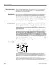
R48, C16, R60, and R64 form the High Voltage Power Supply Current Feedback
circuit. As the current from the High Voltage Power Supply is increased, the
voltage to the + side of the Error Amplifier (U2) increases, which increases the
base drive to Q6, the HV Osc. This current feedback compromises the regula-
tion of the +100 V supply to keep the high voltage constant with varying
intensities.
C66 and Q10 are a Start Delay circuit that holds the Error Amplifier output low,
through CR30, until C66 is charged. Delaying the start of the high voltage
oscillator allows the Low Voltage Power Supply to start, unencumbered by the
load from the high voltage oscillator.
HIGH VOLTAGE POWER
SUPPLY <7>
HV Osc and Error Amp