Performance Check and Calibration Procedures
5–14
760A / 760D / 760N
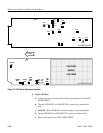
c. ADJUST – R463 (Orthogonality) on the A3 Main board, to align the
trace with the dotted horizontal line.
9. Adjust Vertical Dynamic Stability
a. ADJUST – R782 to eliminate updown motion of the horizontal trace as
the audio generator is turned on and off.
NOTE. If the audio generator is capable of tone burst operation, such as the
TEKTRONIX SG5010, it may be set for one second on one second off tone burst
operation, instead of turning the generator on and off.
10. Adjust Vertical/Horizontal Gain Balance
a. Connect the leveled audio signal generator output to both the RIGHT
and LEFT AUDIO INPUTs. Check that the trace is directly under the R
graticule line.
b. Connect the X1 probes from the oscilloscope differential inputs to
TP885 and TP866.
c. ADJUST – R580 for minimum differential signal (approximately
5 mV).
11. Adjust Horizontal and Vertical Gains
a. Connect the leveled audio signal generator output to both the RIGHT
and LEFT AUDIO INPUTs.
b. Ensure the DISPLAY GAIN control is set to AUTO.
c. ADJUST – R786 (Vertical Gain Adj, on A3) and R759 (Horiz Gain Adj)
so the trace remains directly under the R graticule line (45) and ends at
the center amplitude mark.
12. Adjust CAL Gain
a. Set the front panel DISPLAY GAIN control to CAL.
b. ADJUST – R262 (Cal, on A3) to extend the trace to the end of the R
graticule line.
c. Set the audio signal generator frequency to 20 kHz.
d. ADJUST – R789 (Channel Match, on A3) to close the sides of the
ellipse to a single line (no trace separation).


