


Performance Check and Calibration Procedures
760A / 760D / 760N
5–5
Check the RIGHT and AUXILIARY bars in the same manner, connect-
ing the input signal to one 760A AUDIO INPUT at a time.
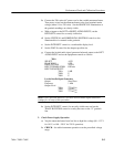
f. (760A only) Set S340 to position 6.
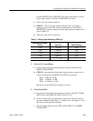
g. CHECK – (760A only) that each bar indicates 0 dB "0.3 dB (6
segments or less from 0 dB) with the combinations of 760A INPUT
SENSITIVITY jumper settings and audio signal generator output levels
given in Table 5–1.
h. (760A only) Set S340 to position 0.
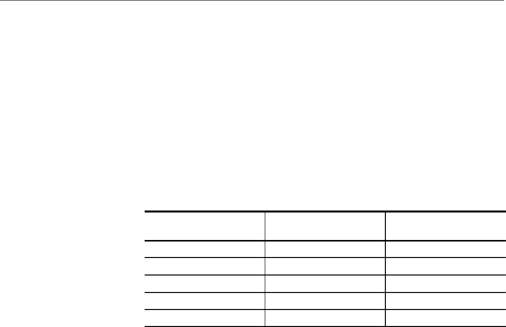
Table 5–1: Verifying Input Sensitivity (760A only)
Input Sensitivity Jumper
Setting
Input Level 760A Bar Reading
+4 dB 1.228 V
rms
0 dB
+8 dB 1.947 V
rms
0 dB
+12 dB 3.085 V
rms
0 dB
+16 dB 4.890 V
rms
0 dB
0 dB 775 mV
rms
0 dB
5. Check AGC Control Range
a. Connect the leveled audio signal generator output to the LEFT and
RIGHT AUDIO INPUTs.
b. CHECK – that when the leveled audio signal generator output level is
varied (as indicated on the RIGHT and LEFT bars) between:
760A: +8dB and –20 dB
760D: +5 dB and –25 dB
760N: +15 dB and –15 dB
that the size of the CRT display changes very little.
6. Check Gain Match
a. Connect the leveled audio signal generator output to the LEFT AUDIO
INPUT and set the DISPLAY GAIN control to CAL.
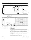
b. Set the leveled audio signal generator output level so the trace ends on
the center amplitude mark of the “L” graticule line. See Figure 2–3 for a
description of the graticule markings.
c. Move the input signal from the LEFT AUDIO INPUT to the RIGHT
AUDIO INPUT.