


Performance Check and Calibration Procedures
5–6
760A / 760D / 760N
d. CHECK – that the trace ends within one–half division of the center
amplitude mark of the “R” graticule line.
7. Check Gain Tracking
a. With the leveled audio signal generator output still connected to the
RIGHT AUDIO INPUT, set the DISPLAY GAIN control to AUTO.
b. Align the trace with the “R” graticule line.
c. CHECK – that when the leveled audio signal generator output level is
varied (as indicated on the RIGHT bar) between:
760A: +8dB and –20 dB
760D : +5 dB and –25 dB
760N : +15 dB and –15 dB
that the trace rotates less than one–half the length of the minor amplitude
mark (the distance from the axis to the end of the minor amplitude
mark). See Figure 2–3 for a description of the graticule.
8. Check Phase Match
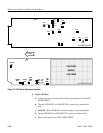
a. Set the 760A for an X–Y display orientation (P273 & P373 on pins 1 &
2, lower pins). Do not change to the X–Y graticule.
b. Connect the leveled audio signal generator output to the LEFT and
RIGHT AUDIO INPUTs.
c. CHECK – that when the leveled audio signal generator frequency is set
at 20 Hz, 500Hz, 1 kHz and 20 kHz, any trace separation is less than one
trace width.
d. Reset the 760A for a “sound stage” display orientation (P273 & P373 on
pins 2 & 3, upper pins).
9. Check CRT Frequency Response
a. Connect the leveled audio signal generator output to the RIGHT AUDIO
INPUT and set the DISPLAY GAIN control to MANual.
b. Set the MANual GAIN control so the trace ends on the center amplitude
mark.
c. CHECK – that when the leveled audio signal generator frequency is
varied from 20 Hz to 20 kHz, the trace length changes less than one
division.