


Theory of Operation
760A / 760D / 760N
6–7
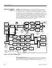
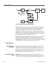
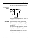
The Low Voltage Power Supply is called a Flyback Switcher. When switcher
mosfet Q9 is turned on, its drain voltage drops to approximately 0 V. The
current through the 350 mH primary winding of T3 begins ramping up. The
voltages present at all secondaries is such that the rectifier diodes are reverse
biased. Energy is being stored in the magnetic field of T3. When Q9 turns off,
the drain voltage “flies back” in a positive direction. Current now flows in all of
the secondary windings and supplies power.
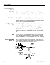
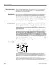
The input line voltage is filtered by the rear-panel connector to reduce the
electrical noise conducted into or out of the instrument. R89 limits the initial
charging current through the rectifier diodes and C54.
CR21, CR22, CR23, and CR24 form a bridge rectifier. C54 filters the 110 to
350 VDC rectifier output. L4 filters the switching noise produced by the
switcher. R102 reduces the circulating current in the parallel circuit consisting of
L4 and C44. DS4, R93, and R94 form a line voltage indicator. R91 and R92
charge C42. C42 provides power to U5 until the primary housekeeping winding
provides power through CR17.
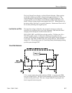
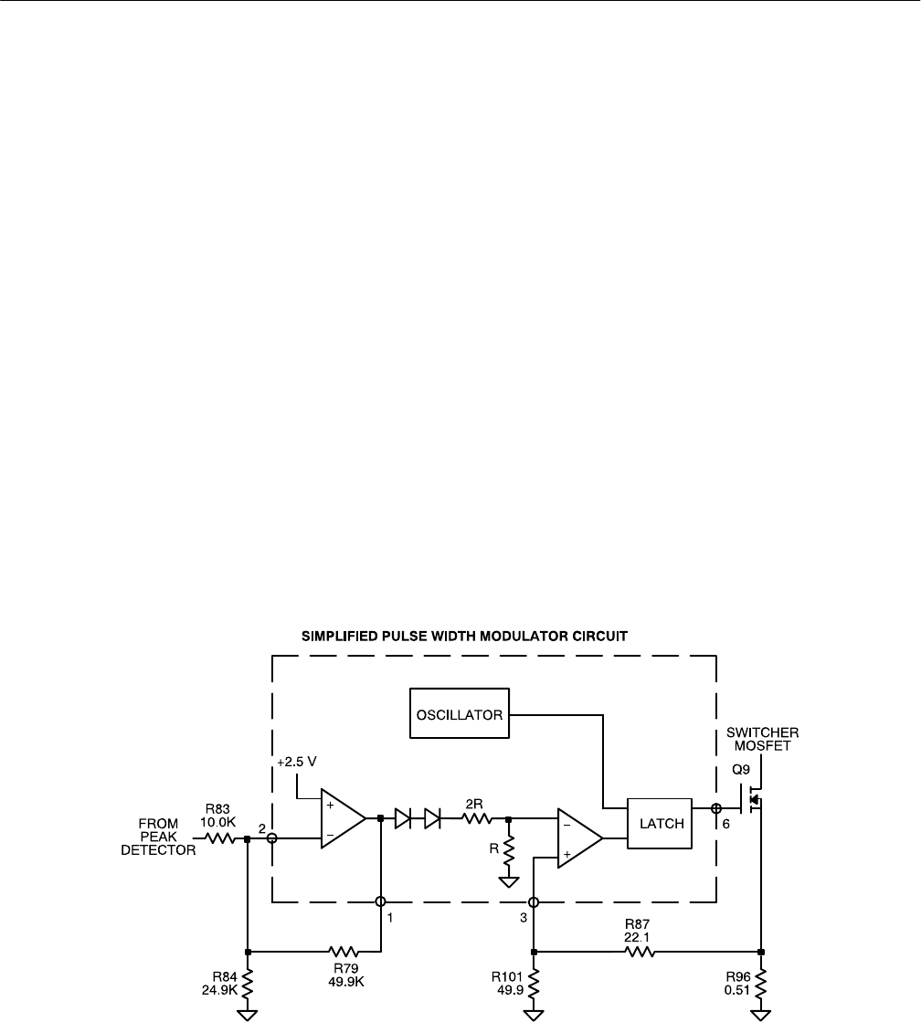
U5 is a current-mode pulse width modulator (PWM). A current-mode PWM
uses two feedback loops. The inner current feedback loop directly controls the
switcher mosfet peak current. The outer voltage feedback loop programs the
inner loop peak current trip point.
Line Rectifier and Filter
Pulse Width Modulator