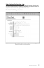
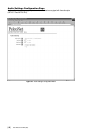
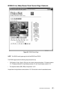
Pelco Manual C1977M-D (6/02) [ 75 ]
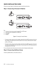
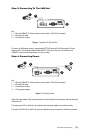
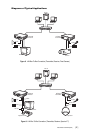
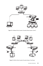
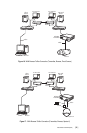
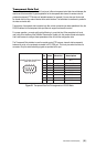
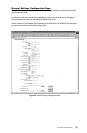
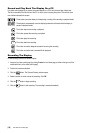
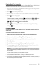
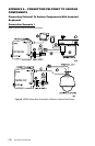
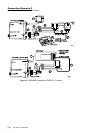
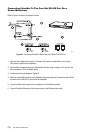
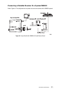
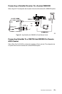
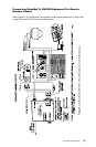
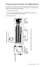
1. Connect a PV130 Converter to the RS-232 port on the front of the PelcoNet Transmission System
receiver. The data format should be 4800 baud, 8 data bits, even parity, and 1 stop bit.
2. Connect the black and white striped wire from the power supply that came with the converter to the
converter’s +12 VDC terminal and the solid black wire to the GND terminal.
3. Connect TD(A) on the converter to terminal 7 on the wall block. Connect TD(B) on the converter to
terminal 8 on the wall block. Connect RD(A) on the converter to terminal 2 on the wall block. Connect
RD(B) on the converter to terminal 1 on the wall block.
4. Connect a straight RJ-45 cable from the wall block to the supplied Pelco power pack.
5. Connect a straight RJ-45 cable from the keyboard input connector on the power pack to COM 1 on
the keyboard.
6. Connect the monitor.
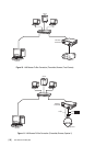
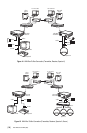
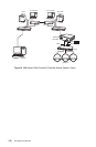
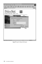
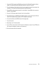
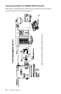
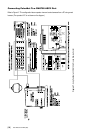
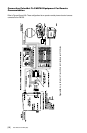
7. Repeat steps 1 and 2 for transmitter.
8. Connect TD(A) on the converter to terminal 2 on the wall block. Connect TD(B) on the converter to
terminal 1 on the wall block. Connect RD(A) on the converter to terminal 7 on the wall block. Connect
RD(B) on the converter to terminal 8 on the wall block.
9. Connect a flipped RJ-45 cable from the wall block to Sercom port 5 on the CC1’s rear panel.
10. Connect one of the three monitor outputs on the rear of the controller to the transmitter.