


Pelco Manual C1977M-D (6/02) [ 13 ]
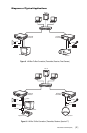
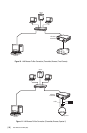
Step 3: Connecting To The LAN Port
1
2
3
1
2
3
4
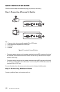
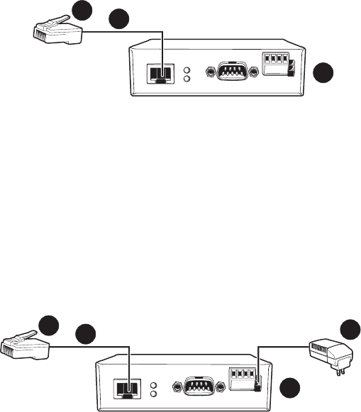
Key:
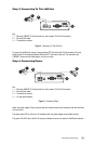
1=Ethernet (10BASE-T) LAN connection to hubs, network, PCs (RJ-45 connector)
2=Ethernet Cat5 cable
3=Transmitter or receiver
Figure 4. Connecting To The LAN Port
To connect to the Ethernet network, use a standard UTP Cat5 cable with RJ-45 connectors. Plug this
cable into the RJ-45 receptacle labeled “Ethernet/UTP” at the rear of the unit. The connection to a
10BASE-T network can be made directly via a hub or switch.
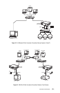
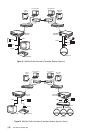
Step 4: Connecting Power
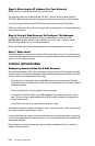
Key:
1=Ethernet (10BASE-T) LAN connection to hubs, network, PCs (RJ-45 connector)
2=Ethernet Cat5 cable
3=Transmitter or receiver
4=AC plug power adapter
Figure 5. Connecting Power
Attach the power adapter. Plug the primary side into the wall outlet and the secondary side with the small
clip into the unit.
The green power LED on the front is lit constantly when the power adapter is connected correctly.
The green LINK LED next to the RJ-45 connector indicates a correct connection to the Ethernet network.