


[ 26 ] Pelco Manual C1977M-D (6/02)
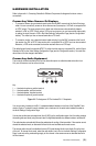
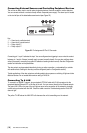
Connecting External Sensors and Controlling Peripheral Devices
The unit has an alarm input to use for external signaling devices, like door contacts or motion detectors.
You can connect switches or contacts directly without a separate power supply. The alarm input is located
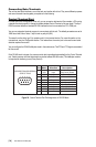
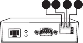
on the two left pins of the detachable screw terminal (see Figure 22).
1 2 3 4
Key:
1=Alarm input, positive terminal
2=Alarm input, ground terminal
3=Relay output, Y
4=Relay output, Z
Figure 22. Pin Assignment Of The I/O Connector
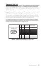
Connecting pin 1 to pin 2 activates the input. You can configure alarm triggering to occur when the contact
between pin 1 and pin 2 closes (normally open) or opens (normally closed). You can also configure alarm
action (for example, connecting to an alarm IP address or sending an alarm e-mail). See the
Configuration
section for information on the possibilities.
The relay output can be operated interactively, during an active connection, or automatically to coincide
with certain events. Settings for the relay must be configured (see the
Configuration
section).
Typical applications of the relay output are activating electric door openers or switching of lights and other
electrical devices. Do not exceed the maximum rating of 24V/0.5A.
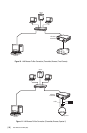
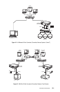
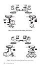
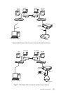
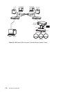
Connecting To A LAN
To connect to a 10BASE-T network, plug a standard UTP/Cat5 cable with RJ-45 connectors into the
receptacle labeled Ethernet/UTP on the rear of the unit. You can connect directly to the Ethernet network.
The green LINK LED on the rear of the unit lights as soon as the connection to the network is physically
correct and synchronized with the LAN. Check the cable or see the
Troubleshooting
section if the LED
does not light.
The yellow TX LED above the LINK LED is lit whenever the unit is transmitting over the network.