


Terminator SS 56 Part No. 1052712 Rev D
PROCEDURE 7
SUSPENSION
SUSPENSION
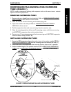
13. Install the rear wheels into the camber inserts. Refer to REMOVING/INSTALLING
REAR WHEELS in PROCEDURE 5 of this manual.
14. Adjust the axle tube. Refer to
ADJUSTING THE AXLE TUBE in PROCEDURE 5 of
this manual.
NOTE: The performance of the wheelchair will be affected if the axle tube has not been adjusted
to correct the toe in/toe out of the wheelchair.
15. Ensure the camber clamps are closed. Refer to OPENING/CLOSING CLAMPS in
PROCEDURE 5 of the manual.
16. Adjust anti-tippers. Refer to ANTI-TIPPER REPLACEMENT/ADJUSTMENT in
PROCEDURE 6 of the manual.
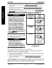
NOTE: QUICK RELEASE LEVERS ONLY - Reposition the quick release levers to the top/bottom of
the axle tube if desired. Refer to REPOSITIONING QUICK RELEASE LEVERS in this procedure of the
manual.
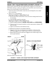
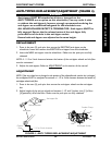
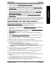
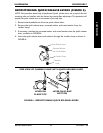
AXLE SUSPENSION CLAMP CLAMP
POSITION TUBE HOLE HOLE POSITION*
TOP A 1 STANDARD
B2
MIDDLE B 1 STANDARD
C2
BOTTOM A 2 INVERTED
B1
NOTE: Tabs on camber clamps shown. Anti-tipper
sockets are not shown for clarity.
NOTE: When viewed from the front of the wheelchair,
inside of the rear wheels, an inverted camber clamp
has the tab or anti-tipper socket at the top of the axle
tube. Refer to DETAIL "A".
Suspension Tube
Hole A
Hole B
FIGURE 5 - REPOSITIONING THE AXLE TUBE
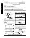
DETAIL "A" - CLAMP POSITION
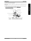
NOTE: Axle tubes are viewed from the FRONT of
the wheelchair.
NOTE: Socket facing DOWN not shown for clarity.
STANDARD CLAMP POSITION -
TABS/SOCKETS
INVERTED CLAMP POSITION - TABS/
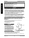
Camber
Clamps
Axle
Tubes
Tab DOWN
DETAIL "B" - MOUNTING HOLE
PATTERN
Hole 2
Hole 1
Camber Clamp
Tab
Axle Tube
Camber
Clamp
Suspension
Tube
Hex Bolt
Locknuts
Camber
Insert
Camber
Clamp
Suspension
Tube
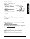
Camber
Clamp
Camber
Clamp
Suspension
Tube
Suspension
Tube
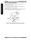
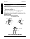
DETAIL "C" - AXLE TUBE POSITIONS
Tab DOWN
Tab DOWN
Tab UP
Socket UP
Tab UP
NOTE: LEFT camber clamp and suspension tube
not shown for clarity.
Camber Clamps
Metal Tabs
Socket DOWN
Axle Tubes
Hole C