


Terminator SS 28 Part No. 1052712 Rev D
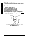
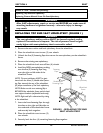
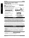
INSTALLING QUAD-RELEASE AXLES (FIGURE 3)
1. Remove rear wheel and the existing quick-release axle from the wheelchair. Refer
to
REMOVING/INSTALLING REAR WHEELS in this section of the manual.
2. Remove existing quick-release axle from rear wheel.
3. Insert new quad-release axle through
rear wheel hub.
4. Slide locking collar onto quad-release
axle until it is snug against rear wheel
and tighten securely with allen screw.
5. Reinstall rear wheel and the quad-
release axle onto the wheelchair.
Refer to REMOVING/INSTALLING
REAR WHEELS in this section of the
manual.
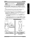
6. Flip the handle of the quad-release axle
down to release the detent pin
ensuring that the locking pins are fully
released.
7. If detent pin does not fully release, proceed to ADJUSTING QUAD-RELEASE
HANDLE IN AND/OR OUT in this section of the manual.
8. Repeat STEPS 1-7 for the opposite rear wheel.
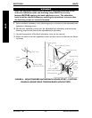
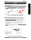
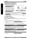
ADJUSTING QUAD-RELEASE HANDLES (FIGURE 4)
IN AND/OR OUT
1. Remove rear wheel and the quad-
release axle from the wheelchair. Refer
to REMOVING/INSTALLING REAR
WHEELS in this section of the manual.
2. Loosen the locking screw.
3. Make the following adjustments:
If the quad-release handle is not
releasing the locking pins
completely, rotate the
quad-release handle approximately
one-quarter (1/4) turn
CLOCKWISE.
If the quad-release handle hits the spokes
of the rear wheel when assembled, rotate
the quad-release handle approximately
one-quarter (1/4) turn
COUNTERCLOCKWISE.
WHEELSSECTION 5
WHEELS
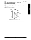
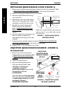
FIGURE 3 - INSTALLING QUAD-
RELEASE AXLES
Adjustable Axle
Position Camber
Bar
Rear Wheel Hub
Quad
Release
Axle
Allen Screw
NOTE: End of Quad Release axle shown for
reference only. It is not visible when inserted
into camber bar
Locking
Collar
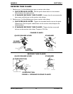
FIGURE 4 - ADJUSTING QUAD-
RELEASE HANDLES
Length
Adjustment
Screw
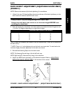
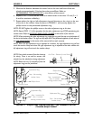
REMOVING
PLAY FROM
REAR
WHEELS
ADJUSTING
QUAD-RELEASE
HANDLE IN/AND
OR OUT
Quad Release
Handle
Locking Pins
Camber Bar
Locking
Screw
Adjusting Locknut
(on Quick-Release
Axle)