


Terminator SS 54 Part No. 1052712 Rev D
SECTION 7 SUSPENSION
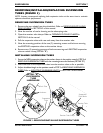
4. Close the receiver tube clamps. Refer to OPENING/CLOSING CLAMPS in SECTION 5
of the manual.
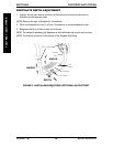
5. Reinstall the rear wheels. Refer to REMOVING/INSTALLING REAR WHEELS in
SECTION 5 of this manual.
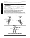
6. Adjust suspension to correspond to the user's weight. Refer to
REPLACING REAR
ELASTOMERS in this section of the manual.
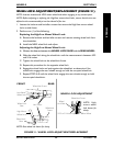
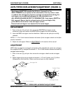
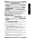
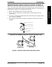
ADJUSTING SEAT-TO-FLOOR HEIGHT (FIGURE 4)
WARNING
The position of the footrest, camber
tube, back angle, the tautness of the
back upholstery as well as the user's
condition are directly related to the
wheelchair's stability. Any change to
one (1) or any combination of the five
(5) may cause the wheelchair to
decrease in stability. Use EXTREME
caution when using a new seating
position. The addition of anti-tippers
may be required. EXTREME care
MUST be taken when changing the
stability of the wheelchair. Refer to the
chart in STABILITY in SECTION 1 of
this manual.
NOTE: Each wheelchair frame has been designed
for a specific size rear wheel. Invacare does not
recommend changing rear wheel size.
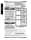
WARNING
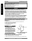
Forks for quick release casters are
available in different sizes to
accommodate spacers. If the
wheelchair is equipped with quick
release casters, DO NOT adjust seat-
to-floor height without changing forks.
Seat-to-floor height is determined by
measuring from the top of the seat rail to the ground/floor.
Several different seat-to-floor heights are possible by using different combinations of
caster size, caster position, and axle tube position.
1. Refer to the chart in FIGURE 4 to determine the axle tube position for the desired
seat-to-floor height adjustment.
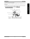
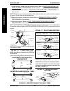
2. Adjust the axle tube position. Refer to REPOSITIONING THE AXLE TUBE in this
section of the manual.
NOTE: After adjusting the axle tube position, the wheelchair frame MUST be parallel to the
ground/floor BEFORE using. It may be necessary to change caster size, caster position, caster
height, wheel lock position and the anti-tipper adjustment (if equipped).
CHANGE OF AXLE
SEAT-TO-FLOOR TUBE
HEIGHT POSITION
LOWER TOP
UPPER Two (2)
Mounting Holes
FACTORY MIDDLE
SETTING
LOWER Two (2)
Mounting Holes
HIGHER BOTTOM
LOWER Two (2)
Mounting Holes
INVERTED
CAMBER CLAMPS
FIGURE 4 - ADJUSTING SEAT-TO-
FLOOR HEIGHT
SUSPENSION