


Part No. 1052712 Rev D 17 Terminator SS
SECTION 3BACK
WARNING
ALWAYS perform this procedure in the presence of an assistant. The
position of the footrest, camber tube, back angle, the tautness of the back
upholstery as well as the user's condition are directly related to the
wheelchairs stability. Any change to one (1) or any combination of the
five (5) may cause the wheelchair to decrease in stability. Use EXTREME
caution when using a new seating position. The addition of anti-tippers
may be required .
After ANY adjustments, repair or service and BEFORE use, make sure all
attaching hardware is tightened securely - otherwise injury or damage
may result.
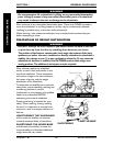
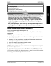
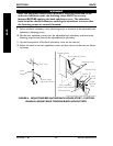
BACK ANGLE ADJUSTMENT (FIGURE 1)
NOTE: This procedure is for fold down back chairs only.
NOTE: DO NOT remove the hex screws that secure the back angle bracket to the chair frame
and back cane.
NOTE: Perform procedure to both sides at the same time.
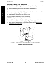
1. Loosen the locknuts and hex screws that secure the back angle bracket to the chair
frame and the back cane.
2. Loosen the TOP hex screw locknut and slide the TOP hex screw away from the
back angle mounting bracket to adjust the cam.
3. Adjust back canes to approximate back angle required.
4. Adjust cam to achieve desired position.
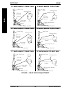
NOTE: An indexing notch has been put on the adjustment cam to help determine cam position
for desired back angle adjustment.
5. Reassemble and torque hex screws to 960-1020 inch-pounds (80-85 foot-pounds).
NOTE: As shown in FIGURE 1, the adjustment cam can be rotated to several different positions
thus changing the overall back angle relative to the seat rail.
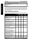
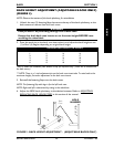
Section 3 - Back - includes the following:
Back Angle Adjustment
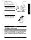
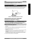
Folding/Unfolding the Back
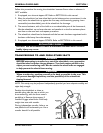
Adjusting/Replacing Back Upholstery
Back Height Adjustment (Adjustable Backs Only)
BACK