


Part No. 1052712 Rev D 55 Terminator SS
SECTION 7SUSPENSION
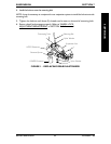
3. If necessary, refer to REPLACING/ADJUSTING CASTERS in PROCEDURE 5 of the
manual to replace the casters or adjust the caster position.
4. After replacing or adjusting the caster size/position, refer to
ADJUSTING FRONT
CASTER HEIGHT in PROCEDURE 5 of the manual to add/remove fork spacers and
add/remove washers to ensure caster headtubes are perpendicular to the ground.
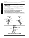
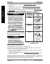
5. Anti-tipper height (if applicable) must be adjusted to maintain 1-1/2 to 2-inch clearance
between the bottom of the anti-tipper wheels and the floor. Refer to
ANTI-TIPPER
REPLACEMENT/ADJUSTMENT in PROCEDURE 6 of this manual.
6. Ensure wheel locks engage properly. Refer to
WHEEL LOCK ADJUSTMENT/
REPLACEMENT in PROCEDURE 5 of the manual.
NOTE: This seat-to-floor chart is based on pneumatic tires and pneumatic tires with flat free
inserts. If wheelchair is equipped with urethane tires, subtract 1/2-inch from the measurements
listed below. All heights are approximate to + 1/4-inch due to tire wear and air pressure.
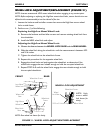
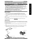
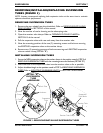
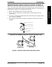
REPOSITIONING THE AXLE TUBE (FIGURE 5)
NOTE: This procedure should only be performed if changing the seat-to-floor height. Refer to
ADJUSTING SEAT-TO-FLOOR HEIGHT in this procedure of the manual.
NOTE: Right and left are determined by standing behind the wheelchair.
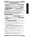
1. Open both the camber clamps. Refer to OPENING/CLOSING CLAMPS in PROCEDURE 5
of the manual.
2. Remove the rear wheels from the wheelchair. Refer to REMOVING/INSTALLING
REAR WHEELS in PROCEDURE 5 of the manual.
3. A4 CAMBER SYSTEM ONLY - Remove the camber inserts from the axle tube
(FIGURE 5).
4. Refer to ADJUSTING SEAT-TO-FLOOR HEIGHT in this procedure of the manual
to determine the proper position for the axle tube.
5. Refer to the chart in DETAIL "C" to determine the proper axle tube adjustment.
NOTE: Refer to DETAIL "B" for suspension tube and clamp hole patterns.
6. Remove the locknuts and hex bolts securing the suspension tubes to the camber clamps.
7. Perform one (1) of the following:
A. CLAMP POSITION MUST BE INVERTED- Proceed to STEP 8.
B. CLAMP POSITION REMAINS IN STANDARD POSITION - Proceed to
STEP 10.
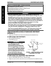
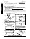
8. Position the LEFT camber clamp onto the RIGHT end of the axle tube with the
metal tabs facing the inside of the wheelchair.
9. Repeat STEP 8 for the RIGHT camber clamp and the LEFT end of the axle tube.
NOTE: The camber clamps should now be inverted, as shown in DETAIL "A".
10. Align the camber clamp mounting holes with the suspension tube holes determined
in STEP 5.
11. Secure suspension tube to camber clamp with hex bolts and locknuts.
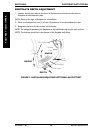
12. A4 CAMBER SYSTEM ONLY - Insert camber inserts into axle tube with lowest
degree of camber facing towards outside of the wheelchair.
SUSPENSION