


Terminator SS 38 Part No. 1052712 Rev D
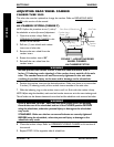
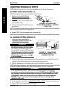
ADJUSTING WHEELBASE WIDTH
NOTE: Perform this procedure one (1) side of the wheelchair at a time for ease of adjustment.
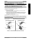
CAMBER TUBE 2000 (FIGURE 14)
NOTE: The wheelbase width can be increased/decreased by 1-inch.
1. Remove the rear wheels. Refer to
REMOVING/INSTALLING REAR
WHEELS in this section of the manual.
2. Torque the axle nut to increase/decrease
the wheelbase width.
3. Count the number of threads showing on
the axle bolt.
NOTE: The number of threads showing on the axle bolt should be equal on both sides of the wheelchair.
Otherwise,wheelchair performance may be affected.
4. Repeat STEPS 2-3 for the opposite axle nut and axle bolt.
NOTE: Axle bolt removed from axle tube for clarity. It is not necessary to remove the axle bolt for this procedure.
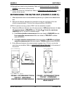
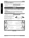
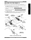
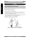
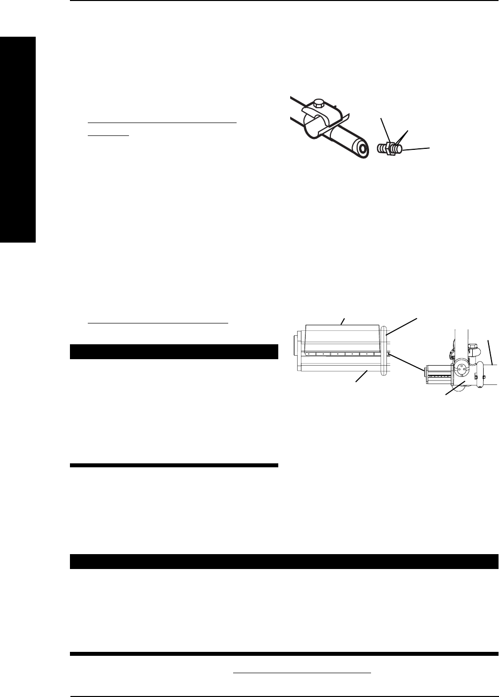
A4 CAMBER SYSTEM (FIGURE 15)
1. Open the camber clamp. Refer to
OPENING/CLOSING CLAMPS in this
section of the manual.
WARNING
NEVER position the camber inserts in
the axle tube with more than 3-inches
(12 indexing marks showing) of the
camber insert outside of the axle tube.
The camber inserts will not be securely
tightened in the axle tube resulting in
possible injury to the user or damage
to the wheelchair.
2. Position camber insert to the desired position. Make sure there is no more than 3-inches (12
indexing marks showing) of the camber inserts outside of the axle tube.
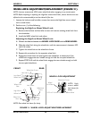
3. Slide the indexing ring on the camber insert until it is flush with the camber clamp.
NOTE: Before using the wheelchair, make sure both camber inserts are set at the same indexing mark. This will
make sure the distance between the rear wheel and the wheelchair is the same on both sides.
WARNING
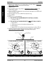
QUICK RELEASE LEVERS - Make sure the quick release levers are pointing
towards the rear of the wheelchair and are in the CLOSED position BEFORE using
the wheelchair, otherwise personal injury or damage to the wheelchair may result.
STANDARD - Make sure the hex screws and locknuts are securely tightened
BEFORE using the wheelchair, otherwise personal injury or damage to the
wheelchair may result.
4. Close the camber clamp. Refer to OPENING/CLOSING CLAMPS in this section of the manual.
5. Repeat STEPS 1-4 for opposite side of wheelchair.
WHEELSSECTION 5
WHEELS
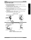
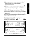
FIGURE 14- ADJUSTING
WHEELBASE WIDTH - CAMBER
TUBE 2000
Axle Bolt
Axle Nut
Threads
FIGURE 15 - ADJUSTING
WHEELBASE WIDTH - A4
CAMBER SYSTEM
Axle
Tube
Indexing Ring
Camber Clamp
Indexing Marks
Camber Insert