


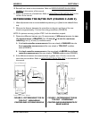

Part No. 1052712 Rev D 41 Terminator SS
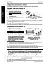
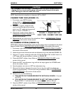
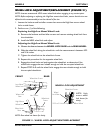
Place "L" Square Here
90° Angle
Flat Edge of Camber
Tube
Ground/
Floor
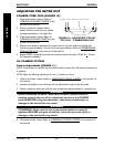
FIGURE 17 - ADJUSTING THE
AXLE TUBE - CAMBER TUBE 2000
CAUTION
A4 CAMBER SYSTEM ONLY - DO NOT close the quick-release levers or
tighten the hex screws and locknuts without camber inserts in the axle
tube. Damage to the axle tube will occur.
NOTE: Stand behind the wheelchair to determine LEFT or RIGHT.
CAMBER TUBE 2000 (FIGURE 17)
1. If necessary, open BOTH camber
clamps. Refer to
OPENING/CLOSING
CLAMPS in this section of the manual.
2. Using an "L" square, rotate the axle
tube until the flat edge of the camber
tube is at a 90° angle with the ground/
floor as shown in FIGURE 17.
3. Close both camber clamps. Refer to
OPENING/CLOSING CLAMPS in this
section of the manual.
4. Determine the toe in/toe out of the wheelchair. Refer to DETERMINING TOE IN/
TOE OUT in this section of the manual.
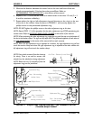
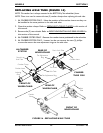
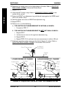
A4 CAMBER SYSTEM (FIGURE 18)
NOTE: Before performing this procedure, make sure the camber inserts are positioned to the lowest
degree of camber. Refer to ADJUSTING REAR WHEEL CAMBER in this section of the manual.
1. If necessary, open BOTH camber clamps. Refer to OPENING/CLOSING CLAMPS in
this section of the manual.
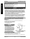
2. Loosen the set screw that secures each toe adjustment ring to the axle tube (FIGURE 18).
3. Using an "L" square, rotate the axle tube until the flat edge of the camber insert is at
a 90° angle with the ground/floor as shown in FIGURE 18.
4. Close the RIGHT camber clamp. Refer to OPENING/CLOSING CLAMPS in this
section of the manual.
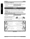
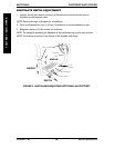
5. Rotate the LEFT toe adjustment ring until the tab stops against the LOWER metal
tab on the camber clamp.
6. Securely tighten set screw on LEFT toe adjustment ring.
7. Measure the distance between the center lines at the rear and front of the rear
wheels at approximately 12-inches from the ground/floor. Refer to DETERMINING
TOE IN/TOE OUT in this section of the manual.
8. Perform one (1) of the following:
A. TOE IN/TOE OUT MEASUREMENT IS WITHIN ±1/8-INCH - Proceed
to STEP 8.
B. TOE IN/TOE OUT MEASUREMENT IS NOT WITHIN ±1/8-INCH -
Repeat STEPS 1-7 until toe in/toe out measurement is within ±1/8 inch.
9. Open the RIGHT camber clamp. Refer to OPENING/CLOSING CLAMPS in this
section of the manual.
WHEELS SECTION 5
WHEELS