


FURUNO
BR-500
SPECIFICATIONS OF BRIDGE NAVIGATIONAL WATCH ALARM SYSTEM
BR-500
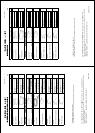
1 MAIN ALARM PANEL (BR-510)
1.1 Display 4.3-inch color LCD, 480 x 272 dots
1.2 Brilliance 0.15 to 500 cd/m
2
(w/o shield film)
1.3 Status indication Dormant period, Alarm stage, Backup officer, Power status,
Operation mode
1.4 Other functions Backup officer selection, Emergency call, Officer call
2 PROCESSOR UNIT (BR-520)
2.1 Input port
Operator fitness 4 ch (normal open)
Autopilot mode 1 ch (normal open)
Backup navigator 1 ch (normal close)
2.2 Output port
System failure 2 ch (normal close)
2.3 Serial signal 1 ch (for VDR)
2.4 Cabin panel control 12 sets max. (3 sets: cascade connection)
2.5 Timer reset panel control 6 sets max. (2 sets: cascade connection)
2.6 Motion detector 2 ch
2.7 Flash beacon 3 ch
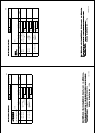
3 CABIN PANEL (BR-540)
3.1 Input voltage 12 VDC: 100 mA or less (supplied from processor unit)
3.2 Visible indication Alarm LED, Duty LED
3.3 Audible alarm Buzzer
3.4 Wire breaking diagnose Press button
3.5 Dimmer Inner volume and linked with key light
4 TIMER RESET PANEL (BR-530)/ WATERTIGHT TIMER RESET PANEL (BR-550)
4.1 Visible indication Alarm LED, Reset LED
4.2 Audible alarm Buzzer
4.3 Timer reset Press button (yellow)
4.4 Wire breaking diagnose Continuing pressure of button
4.5 Dimmer Inner volume and linked with key light
5 MOTION DETECTOR (BR-560, OPTION)
5.1 Detection method Infrared body motion sensor
5.2 Distance 5 m
5.3 Angle ±40°
5.4 Object size 700 mm x 250 mm (minimum)
SP - 1 E4461S01F
110517