


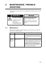

3. MAINTENANCE, TROUBLESHOOTING
3-3
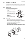
3.4 How to Check Connection Between Processor
Unit/Cabin Panel/ Timer Reset Panel
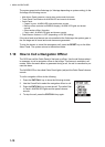
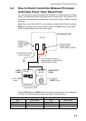
You can check the connection between the Processor Unit/Cabin Panel/Timer Reset
Panel. The tested panel sends a test signal to the Processor Unit. The Processor Unit
receives the test signal then commands that panel to light or flash its LEDs and sound
its buzzer.
Note: If the 4-core cable (MPYC-4, or equivalent) connects Cabin Panel(s), use the
EMG call on the Main Alarm Panel to do the check. The TEST switch on the Cabin
Panel is disabled when the 4-core cable is used.
Push the TEST switch or RESET button (long-push) to start the test. The tested panel
is normal if its LEDs and buzzer perform as shown in the table below.
Note 1: The watch timer is not reset during the test.
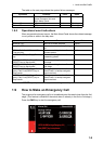
Cabin Panel Timer Reset Panel
Item Normal State Item Normal State
ALARM LED Lights 5 s ALARM LED Flashes 5 s
DUTY LED Lights 5 s RESET LED Lights
Buzzer 5 s Buzzer 5 s
(4) LED lights or flashes
and buzzer sounds.
PROCESSOR UNIT
CABIN
PANEL
BR-520
Test channel for
CABIN PANEL,
TIMER RESET PANEL
(2) Test signal is sent on
test channel of CABIN PANEL,
TIMER RESET PANEL
(1) Push TEST
switch.
BR-540
Channel for
CABIN PANEL,
TIMER RESET
PANEL
BR-530/
BR-550
TIMER RESET
PANEL
(1) Long-push
RESET button.
(3) PROCESSOR UNIT
sends test signal.