


4. INSTALLATION
4-16
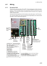
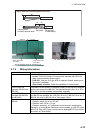
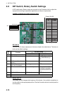
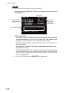
4.8 DIP Switch, Rotary Switch Settings
A DIP switch and a Rotary switch are provided in the Processor Unit to adjust the
equipment according to applicable regulations and ship’s requirements.
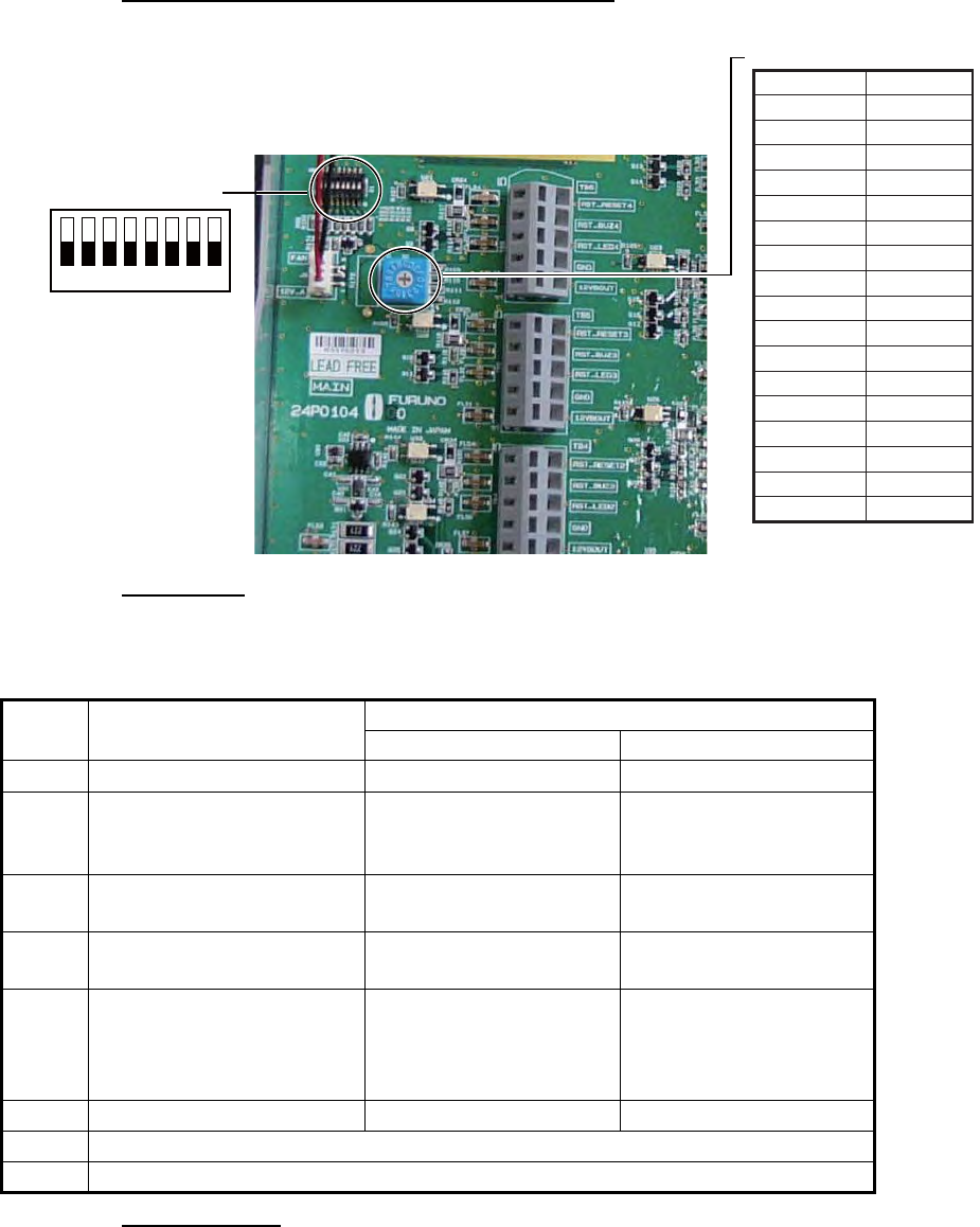
Location of switches in the Processor Unit
DIP SW S1
The DIP SW S1 allows adjustment of the items listed in the table below. The items in
bold are the default settings.
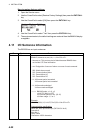
Rotary SW S2
The Rotary SW S2 changes the frequency of the buzzer. Use a plastic screwdriver to
turn the switch to the appropriate position. See the illustration above for switch position
and frequency.
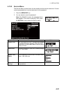
SW
No.
Function
DIP SW Setting
OFF ON
1 Boot program overwrite Enabled Disabled
2 I/O test Disabled All LEDs, System Fail
and Flash Beacon go
ON.
3 ALR output (fixed interval
output)
30s 60s
4 Flash Beacon function
(2nd and 3rd stages)
Flashing OFF
5 Processor Unit startup Normal startup Startup disabled. (For
updating the program of
the MAIN ALARM PAN-
EL.)
6 IEC 61162 Baud rate 4800 (bps) 38400 (bps)
7 No use
8 No use
0 4.2 kHz
1 4.15 kHz
2 4.25 kHz
3 4.2 kHz
4 4.2 kHz
5 4.2 kHz
6 4.2 kHz
7 4.2 kHz
8 4.2 kHz
9 4.2 kHz
0 4.2 kHz
A 4.2 kHz
B 4.2 kHz
C 4.2 kHz
D 4.2 kHz
E 4.2 kHz
F 4.2 kHz
SW position Frequency
Rotary SW S2
Default setting in bold italic
DIP SW S1
ON
1 2 3 4 5 6 7 8