


4. INSTALLATION
4-12
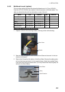
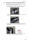
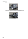
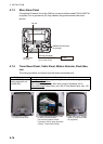
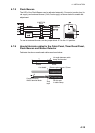
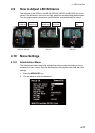
How to fabricate and fix cables to the Processor Unit
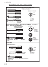
L 3
L=Distance from cable clamp
to terminal connection
Armor
Sheath
Cut sheath.
6
Connect cores to
WAGO terminal
block.
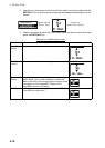
MPYC-2
φ
= 10.0 mm
Armor
Insulator
Sheath
Conductor
S = 1 mm
2
φ = 1.29 mm
MPYC-4
φ
= 11.2
mm
MPYC-7
φ
= 13.2
mm
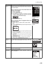
DPYC-1.5: φ = 11.7 mm
DPYC-2.5: φ = 12.8 mm
Armor
Sheath
Conductor
DPYC-1.5:
S = 1.5 mm
2
φ = 1.56 mm
DPYC-2.5:
S = 2.5 mm
2
φ = 2.01
mm
L=Distance from cable clamp
to terminal connection
L=Distance from cable clamp
to terminal connection
Remove paint.
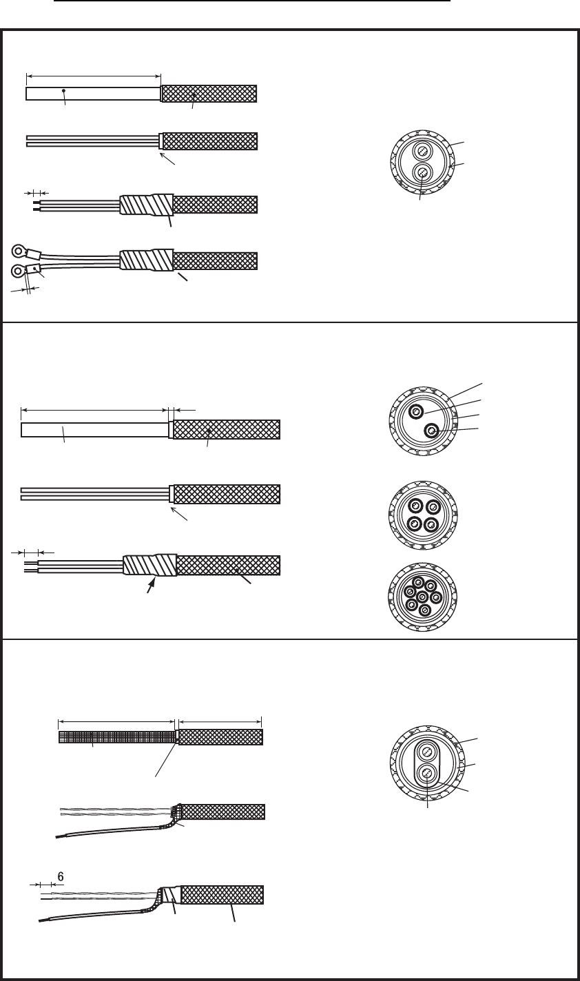
L 50
Shield
Cut vinyl sheath.
Pull out cables from shield;
solder vinyl wire to shield.
Vinyl tape
Set this part in cable clamp.
TTYCS-1
φ = 10.1 mm
Armor
Sheath
Shield
Conductor
S = 0.75 mm
2
φ = 1.11 mm
Power cables for Processsor Unit (DPYC-1.5 (AC power), DPYC-2.5 (DC power))
MPYC-2 (Operator Fitness), MPYC-4
*1
(Motion Detector, Flash Beacon)
MPYC-7
*2
(Cabin Panel, Timer Reset Panel)
TTYCS-1 (VDR)
Crimp-on lug
Inner diameter
φ
4
Outer diameter
φ
7
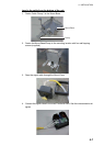
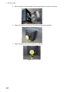
Set this part in
cable clamp.
Connect cores to
WAGO terminal
block.
*1
Also available for
Cabin Panel connection.
*2
Use MPYCY-7 for
Watertight Cabin
Panel.
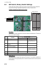
Vinyl tape
Set this part in
cable clamp.
L
6
Armor
Cut the sheath.
Vinyl tape
Sheath
1