


4. INSTALLATION
4-11
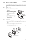
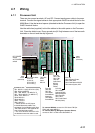
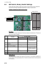
4.7 Wiring
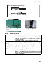
4.7.1 Processor Unit
There are two power terminals: AC and DC. Connect each power cable to its power
terminal. Connect the signal cables to their appropriate WAGO terminal blocks on the
MAIN Board. Use the terminal opener (attached inside the Processor Unit) to open the
WAGO terminal blocks.
Use the cable ties (supplied) to bind the cables to the cable posts on the Processor
Unit. Close the shield cover. Run a ground wire (IV-2sq) between one of the two earth
terminals on the unit and the ship’s ground.
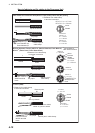
TB1: DPYC-1.5 (AC), DPYC-2.5 (DC)
TB2: FRU12-05AFFM
TB3 - TB6: MPYC-7 (or MPYCY-7)
TB7 - TB15: MPYC-7 (or MPYC-4*
2
)
TB16, TB17: MPYC-4
TB18: MPYC-2
TB19: MPYC-4
TB20: TTYCS-1
TB21: MPYC-2
*
1
Cables shown are JIS (Japan
Industrial Standard) cables. Use
equivalent if not available locally. See
“JIS Cable Guide” in the Appendix for
how to find equivalent cable.
*
2
The TEST function and DUTY LED
are disabled when this cable is used.
TB2: Main
Alarm
Panel
BR-51
0
From Top:
TB6, TB5
TB4, TB3:
Timer Reset
Panel BR-530,
Watertight
Timer Reset
Panel BR-550
From Top:
TB12, TB11,
TB10, TB9,
TB8, TB7:
Cabin Panel
BR-540
(Backup
Officer)
From Top:
TB17: Motion
Detector BR-560,
Backup Navigator
TB16: Autopilot
TB15, TB14,
TB13: Cabin Panel
BR-540 (Public)
From Top:
TB21: Operator Fitness,
TB20: VDR, Other
TB19: Flash Beacon BR-570
TB18: Alarm System, VDR
Cables to use *
1
TB1: Power cables
From Left:
#1, #2: AC
#3: 24 VDC (+)
#4: 24 VDC (-)
PWR
Board
(24P0105)
MAIN
Board
(24P0104)
A
C POWER
switch
DC POWER
switch
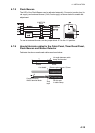
To connect BR-560, connect it to TB 16 and TB17(or
TB21) with cable MPYC-4.
To connect Back-up Navigator, Operator fitness,
connect to TB17 or TB21 with cable MPYC-2.