


4. INSTALLATION
4-14
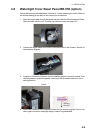
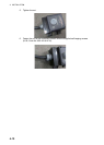
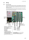
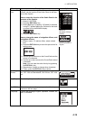
4.7.3 Main Alarm Panel
Connect the Processor Unit to the CAN bus connector with the cable FRU12-05AFFM
(supplied). Run a ground wire (IV-2sq) between the ground terminal and ship’s
ground.
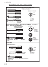
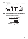
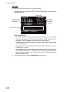
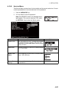
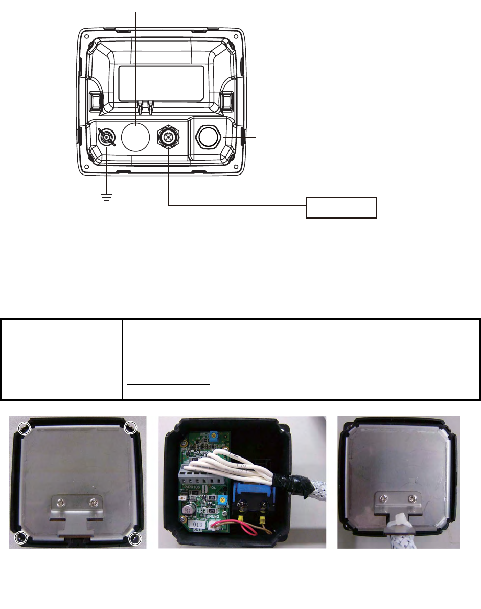
4.7.4 Timer Reset Panel, Cabin Panel, Motion Detector, Flash Bea-
con
The wiring procedure is common to all the above-mentioned units.
Cable to use Description
Cable MPYC-7 (be-
tween respective unit
and BR-520)
Timer Reset Panel
Max. length of single cable: 40 m Max. length: of all ca-
bles: 150 m Cabin Panel
Max. length of single cable: 80 m Max. length of all cables: 300 m
Cable total length
Cabin Panel: max. 300 m Timer Reset Panel: max. 150
m
Ground Wire
(IV-2sq)
Cable FRU12-05AFFM
(10 m, max. 50 m)
Processor Unit
BR-520
CAN bus connector
No use
NMEA 0183 connector
(for service)
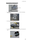
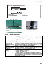
1) Loosen four screws
to remove rear cover.
2) Process cable and connect cable
to WAGO terminal block.
Use terminal opener (inside
Processor Unit) to open terminals.
(Shown: Timer Reset Panel)
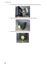
3) Close rear cover. Fasten
cable to clamp with cable
tie (supplied).