


5 • Troubleshooting and maintenance Model 3095 mDSL DACS Getting Started Guide
60 Maintenance
2. Unplug both male power cable connectors from their outlets.
3. Rotate the power cord retainer clips out of the way, then remove both power cables from the malfunction-
ing Model 3095.
4. Disconnect and label the following cables from the malfunctioning Model 3095:
– the T1/E1 WAN cables
– the RS-232 CONFIG cable
– the 10/100 ETHERNET cable
5. Disconnect the ground wire from the grounding stud.
6. If the Model 3095 is mounted in a rack, remove it from the rack.
7. Place the malfunctioning Model 3095 in the container that the replacement Model 3095 came in so you
can return the Model 3095 for repair.
Installing the replacement Model 3095
1. If you are installing the replacement Model 3095 in a 19-inch rack, go to step 2. Otherwise, place the
Model 3095 at the desired location, then go to step 5.
2. Install the rack mounting ears onto the Model 3095 using the mounting hardware provided.
3. Place the Model 3095 at the desired position in the rack.
4. Secure the Model 3095 in position with the mounting screws.
5. Install the ground wire onto the grounding stud.
6. Connect the following cables onto the Model 3095:
– the T1/E1 WAN cables
– the RS-232 CONFIG cable
– the 10/100 ETHERNET cable
7. Install the power cable into their IEC-320 connectors.
8. Rotate the power cable retainer clips so they secure the power cable plugs in the IEC-320 connectors.
Verifying the hardware installation
1. Connect the male end of the power cord to a power distribution strip or to a wall outlet.
2. Verify that the green POWER LED is lit.
Importing a saved configuration
Before the Model 3095 can be configured, the IP address and the netmask needs to be set up. This setup is
done through the Model 3095 RS-232 CONFIG port on the Model 3095.
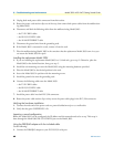
Using the DB9-RJ45 adapter with the included cable
Do the following:
1. Connect the DB9-RJ45 adapter to your PC’s RS-232 serial port