


2 • Hardware installation Model 3095 mDSL DACS Getting Started Guide
28 Completing the hardware installation
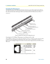
2. The other end of the cable has 68 unterminated twisted-pairs for connection to a punch-down block.
Select the twisted pairs for the WAN ports that will be activated and terminate them on the punch-down
block.
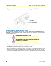
Connecting the mDSL Ports
The remote (CPE) mDSL modems are connected to the DACS via the RJ-21X cable. Consult Appendix A,
“‘Network Ports (RJ-21X) connector pin-out” in order to connect the CPE mDSL modems to the selected
mDSL modem port on the 3095.
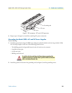
Note The 2-wire mDSL modem lines are polarity insensitive so you only
need to match the correct twisted pairs without being concerned
about matching the individual wires of the twisted pair.
1. Connect the RJ-21X connector of the cable into the 50-pin RJ-21X receptacle on the rear of the 3095.
2. The other end of the cable has 25 non-terminated twisted-pairs for connection to punch-down blocks.
Select the twisted-pairs which will be used for active mDSL modem connections and terminate on the
punch-down blocks. Only 16 of the twisted pairs will be used since there are 16 mDSL modem connec-
tions, each being a 2-wire connection.
3. Select and attach the appropriate twisted pair from each remote (CPE) mDSL modem on punch-down
blocks for connection to the chosen mDSL port in the 3095.
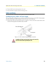
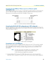
Completing the hardware installation
This section verifies that the DACS hardware is operational to the point where you can begin configuring the
software settings. For AC units, do the following:
1. Verify that the AC power cord included with your DACS is compatible with local standards. If it is not,
refer to Chapter 6, “Contacting PATTON for assistance” to find out how to replace it with a compatible
power cord.
2. Connect the male end of the power cord to an appropriate power outlet.
3. Verify that the green POWER LED is lit. If the POWER LED is flashing
green, refer to Chapter 5, “Trou-
bleshooting and maintenance”.
Hardware installation is complete. Refer to Chapter 3, “Configuring the DACS for operation”.
For DC units, do the following:
The DACS power supply automatically adjusts to accept an input
voltage from 100 to 240 VAC (50/60 Hz), 1.5A.
Verify that the proper voltage is present before plugging the
power cord into the receptacle. Failure to do so could result in
equipment damage.
An approved external power supply that incorporates a disconnect device
must be used and positioned within easy reach of the operator's position.