


3 • Configuring the DACS for operation Model 3095 mDSL DACS Getting Started Guide
46 Using a Web browser to complete Model 3095 configuration
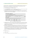
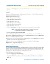
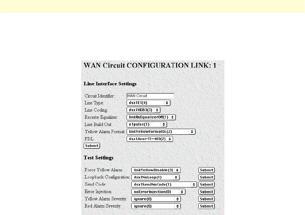
2. View Link 1 corresponds to the first Wan circuit on the DACS. Beside View Link 1-4 click on View Links,
Configuration then Modify. The Line Interface Settings of the WAN Circuit Configuration window appears
(see figure 26).
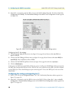
Figure 26. WAN Circuit Configuration window, Line Interface Settings section
Configuring the E1 line settings
1. Click on the Line Type pull-down menu (see figure 26 on page 46) and choose either
dsx1EX(1)
or
dsx1E1-CRC(5)
.
2. Click on the
Line Coding pull-down menu (see figure 26 on page 46) and choose either
dsx1AMI(5)
or
dsxHDB3(3)
. Most installations will use HDB3.
3. Click on the
Line Build Out pull-down menu (see figure 26 on page 46) and select
e1pulse(1)
.
4. Click on
Submit Query.
At this point, the WAN front panel LEDs will become active. A solid green FRAME light indicator means that
the DACS has synchronized with the E1 line. If the E1 line is not connected to the 3095, you will see Alarms
on that WAN port. These should disappear upon connecting the E1 line to the WAN port on the rear of the
Model 3095.
Configuring line settings and signaling for T1
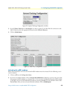
1. Select T1/E1 Link on the Configuration Menu. The T1/E1 Link Activity Overview window appears (see
figure 25 on page 45).
2.
View Link 1 corresponds to the first WAN circuit on the DACS. Click on View Link 1, then on Modify
Configuration. The Line Interface Settings section of the WAN Circuit Configuration window appears (see
figure 25 on page 45).