


Hardware overview 19
Model 3095 mDSL DACS Getting Started Guide 1 • Introduction
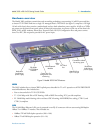
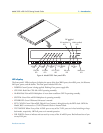
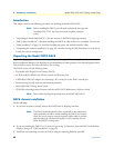
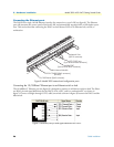
Figure 4. Model 3095 front panel LEDs
LED display
The front panel's LEDs (see figure 4) display the status of the four WAN ports, the mDSL ports, the Ethernet
LAN port, power, and the alarms. The front panel includes LEDs for:
• POWER: Green if power is being applied. Flashing if one power supply fails.
• CPU FAIL: Red if the CPU fails. Off if operating normally.
• ALARM: Red if the mDSL Multiplexer is in an alarm condition. OFF if operating normally.
• SYSTEM: Green if the mDSL Multiplexer is operating normally.
• ETHERNET: Green if Ethernet link status is normal.
• EXT. CLOCK: Green if the mDSL Digital Cross Connect is being driven by the BITS clock. Off if the
Model 3095 is connected to a (T1/E1) Network Clock or Internal Clock.
• TEST MODE: Yellow if any of the 16 DSL ports or any of the T1/E1 ports are in local switching or loop-
back mode, respectively. Off if all ports are in normal operation.
• DSL PORTS: Green to indicate end-user activity on any of the 16 mDSL ports. Red indicates loss of sync
on any DSL port.
U
N
IT
E
Q
U
IP
P
E
D
W
IT
H
D
U
A
L
S
U
P
P
L
IE
S
D
IS
C
O
N
N
E
C
T
B
O
T
H
S
U
P
P
L
IE
S
B
E
F
O
R
E
S
E
R
V
IC
IN
G
U
N
IT
E
Q
U
IP
P
E
D
W
IT
H
D
U
A
L
S
U
P
P
L
IE
S
D
IS
C
O
N
N
E
C
T
B
O
T
H
S
U
P
P
L
IE
S
B
E
F
O
R
E
S
E
R
V
IC
IN
G
4321
R
e
m
o
te
A
c
c
e
s
s
S
e
rv
e
r
MODEL 2960
A
L
A
R
M
S
Y
S
T
E
M
E
T
H
E
R
N
E
T
C
P
U
F
A
I
L
P
O
W
E
R
C
A
L
L
S
A
C
T
C
A
L
L
A
C
T
N
O
S
I
G
N
A
L
E
R
R
O
R
F
R
A
M
E
4321
W
A
N
P
O
R
T
S
POWER
LED
ALARM
LED
ETHERNET
LED
CPU FAIL
LED
SYSTEM
LED
EXT CLOCK
LED
DSL enabled
LED
TEST MODE
LED
EXP enabled
LED
WAN enabled
LED
DSL error
LED
EXP error
LED
WAN error
LED