8XC196NP, 80C196NU USER’S MANUAL
3-2
3.2 OPERATING MODES
The accumulator has two operating modes that allow you to control the results of operations on
signed numbers. These modes are called saturation mode and fractional mode.
3.2.1 Saturation Mode
Saturation occurs when the result of two positive numbers generates a negative sign bit or the re-
sult of two negative numbers generates a positive sign bit. Without saturation mode, an underflow
or overflow occurs and the overflow (OVF) flag is set. Saturation mode prevents an underflow or
overflow of the accumulated value. In saturation mode, the accumulator’s value is changed to
7FFFFFFFH for a positive saturation or 80000000H for a negative saturation and the sticky sat-
uration (STSAT) flag is set. The following two examples illustrate the contents of the accumulator
as a result of positive and negative saturation, respectively:
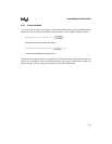
7FFFFFFFH = 0111 1111 1111 1111 1111 1111 1111 1111 = 2
31
– 1 = +2147483647
80000000H = 1000 0000 0000 0000 0000 0000 0000 0000 = –2147483648
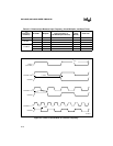
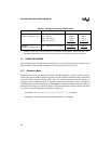
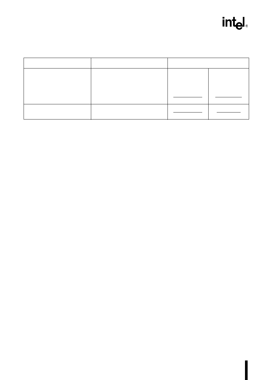
Table 3-1. Multiply/Accumulate Example Code
Device Instructions Execution Time
8XC196NP
(25 MHz; 1 state time = 80 ns)
mul temp,operand_2,operand_1
shll temp,#1
add out_l,temp_l
addc out_h,temp_h
16 states
8 states
4 states
4 states
32 states total
1280 ns
640 ns
320 ns
320 ns
2560 ns total
80C196NU
(50 MHz; 1 state time = 40 ns)
mul 08H,operand_2,operand_1
†
16 states
16 states total
640 ns
640 ns total
†
Because bit 3 of the destination address (08H) is set, the 80C196NU clears the accumulator before
adding the result of the current instruction to it. If bit 3 were clear (destination address 07H–00H), the
80C196NU would add the result of the current instruction to the existing value of the accumulator.


