8XC196NP, 80C196NU USER’S MANUAL
6-4
6.3 INTERRUPT SOURCES AND PRIORITIES
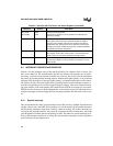
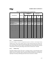
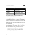
Table 6-3 lists the interrupts sources, their default priorities (30 is highest and 0 is lowest), and
their vector addresses. The unimplemented opcode and software trap interrupts are not priori-
tized; they go directly to the interrupt controller for servicing. The priority encoder determines
the priority of all other pending interrupt requests. NMI has the highest priority of all prioritized
interrupts, PTS interrupts have the next highest priority, and standard interrupts have the lowest.
The priority encoder selects the highest priority pending request and the interrupt controller se-
lects the corresponding vector location in special-purpose memory. This vector contains the start-
ing (base) address of the corresponding PTS control block (PTSCB) or interrupt service routine.
PTSCBs must be located on a quad-word boundary in the internal register file. Interrupt service
routines must begin execution in page FFH, but can jump anywhere after the initial vector is tak-
en.
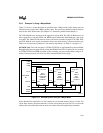
6.3.1 Special Interrupts
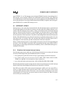
This microcontroller has three special interrupt sources that are always enabled: unimplemented
opcode, software trap, and NMI. These interrupts are not affected by the EI (enable interrupts)
and DI (disable interrupts) instructions, and they cannot be masked. All of these interrupts are
serviced by the interrupt controller; they cannot be assigned to the PTS. Of these three, only NMI
goes through the transition detector and priority encoder. The other two special interrupts go di-
rectly to the interrupt controller for servicing. Be aware that these interrupts are often assigned to
special functions in development tools.
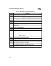
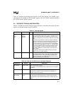
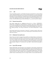
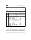
INT_PEND
INT_PEND1
0009H
0012H
Interrupt Pending Registers
The bits in this register are set by hardware to indicate that an
interrupt is pending.
PSW No direct access Processor Status Word
This register contains one bit that globally enables or disables
servicing of all maskable interrupts and another that enables or
disables the PTS. These bits are set or cleared by executing the
enable interrupts (EI), disable interrupts (DI), enable PTS (EPTS),
and disable PTS (DPTS) instructions.
PTSSEL 0004H, 0005H PTS Select Register
This register selects either a PTS routine or a standard interrupt
service routine for each of the maskable interrupt requests.
PTSSRV 0006H, 0007H PTS Service Register
The bits in this register are set by hardware to request an end-of-
PTS interrupt.
Table 6-2. Interrupt and PTS Control and Status Registers (Continued)
Mnemonic Address Description


