8XC196NP, 80C196NU USER’S MANUAL
2-6
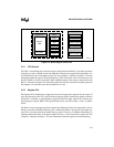
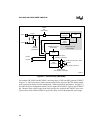
The extended program counter (EPC) is an extension of the slave PC. The EPC generates the up-
per eight address bits for extended code fetches and outputs them on the extended addressing port
(EPORT). Because only four EPORT pins are implemented, only the lower four address bits are
available. (See Chapter 5, “Memory Partitions,” for additional information.)
The memory controller includes a chip-select unit with six chip-select outputs for selecting an ex-
ternal device during an external bus cycle. During an external memory access, a chip-select out-
put is asserted if the address falls within the address range assigned to that chip-select. The bus
width, the number of wait states, and multiplexed or demultiplexed address/data lines are pro-
grammed independently for the six chip-selects. The address range of the chip-selects can be pro-
grammed for various granularities: 256 bytes, 512 bytes, … 512 Kbytes, or 1 Mbyte. The base
address can be any address that is evenly divisible by the selected address range. See Chapter 13,
“Interfacing with External Memory,” for more information.
2.3.5 Multiply-accumulate (80C196NU Only)
The 80C196NU is able to process multiply-accumulate operations through the use of a hardware
accumulator and enhanced multiplication instructions. The accumulator includes a 16-bit adder,
a 3-to-1 multiplexer, a 32-bit accumulator register, and a control register. The multiply-accumu-
late function is enabled by any 16-bit multiplication instruction with a destination address that is
in the range 00–0FH. The instructions can operate on signed integers, unsigned integers, and
signed fractional numbers. The control register allows you to enable saturation mode and frac-
tional mode for signed multiplication. Chapter 3, “Advanced Math Features,” describes the accu-
mulator.
2.3.6 Interrupt Service
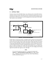
The device’s flexible interrupt-handling system has two main components: the programmable in-
terrupt controller and the peripheral transaction server (PTS). The programmable interrupt con-
troller has a hardware priority scheme that can be modified by your software. Interrupts that go
through the interrupt controller are serviced by interrupt service routines that you provide. The
peripheral transaction server (PTS), a microcoded hardware interrupt processor, provides high-
speed, low-overhead interrupt handling. You can configure most interrupts (except NMI, trap,
and unimplemented opcode) to be serviced by the PTS instead of the interrupt controller.
The PTS can transfer bytes or words, either individually or in blocks, between any memory loca-
tions and can generate pulse-width modulated (PWM) signals. PTS interrupts have a higher pri-
ority than standard interrupts and may temporarily suspend interrupt service routines. See
Chapter 6, “Standard and PTS Interrupts,” for more information.


