6-3
STANDARD AND PTS INTERRUPTS
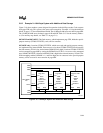
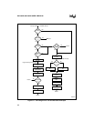
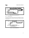
Figure 6-1 illustrates the interrupt processing flow. In this flow diagram, “INT_MASK” repre-
sents both the INT_MASK and INT_MASK1 registers, and “INT_PEND” represents both the
INT_PEND and INT_PEND1 registers.
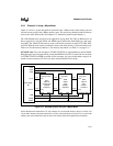
6.2 INTERRUPT SIGNALS AND REGISTERS
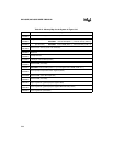
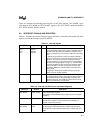
Table 6-1 describes the external interrupt signals and Table 6-2 describes the control and status
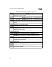
registers for both the interrupt controller and PTS.
Table 6-1. Interrupt Signals
Port Pin Interrupt Signal Type Description
P2.2
P2.4
P3.6
P3.7
EXTINT0
EXTINT1
EXTINT2
EXTINT3
I External Interrupts
In normal operating mode, a rising edge on EXTINT
x
sets the
EXTINT
x
interrupt pending bit. EXTINT
x
is sampled during
phase 2 (CLKOUT high). The minimum high time is one state
time.
In standby and powerdown modes, asserting the EXTINT
x
signal for at least 50 ns causes the device to resume normal
operation. The interrupt need not be enabled, but the pin
must be configured as a special-function input (see “Bidirec-
tional Port Pin Configurations” on page 7-7). If the EXTINT
x
interrupt is enabled, the CPU executes the interrupt service
routine. Otherwise, the CPU executes the instruction that
immediately follows the command that invoked the power-
saving mode.
In idle mode, asserting any enabled interrupt causes the
device to resume normal operation.
— NMI I Nonmaskable Interrupt
In normal operating mode, a rising edge on NMI generates a
nonmaskable interrupt. NMI has the highest priority of all
prioritized interrupts. Assert NMI for greater than one state
time to guarantee that it is recognized.
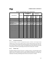
Table 6-2. Interrupt and PTS Control and Status Registers
Mnemonic Address Description
EPA_MASK 1FA0H, 1FA1H EPA Interrupt Mask Register
This register enables/disables the four capture overrun interrupts
(OVR0-3).
EPA_PEND 1FA2H, 1FA3H EPA Interrupt Pending Register
The bits in this register are set by hardware to indicate that a
capture overrun has occurred.
INT_MASK
INT_MASK1
0008H
0013H
Interrupt Mask Registers
These registers enable/disable each maskable interrupt (that is,
each interrupt except unimplemented opcode, software trap, and
NMI).


