6-1
CHAPTER 6
STANDARD AND PTS INTERRUPTS
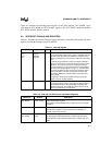
This chapter describes the interrupt control circuitry, priority scheme, and timing for standard and
peripheral transaction server (PTS) interrupts. It discusses the three special interrupts and the four
PTS modes, two of which are used with the EPA to produce pulse-width modulated (PWM) out-
puts. It also explains interrupt programming and control.
6.1 OVERVIEW OF INTERRUPTS
The interrupt control circuitry within a microcontroller permits real-time events to control pro-
gram flow. When an event generates an interrupt, the device suspends the execution of current
instructions while it performs some service in response to the interrupt. When the interrupt is ser-
viced, program execution resumes at the point where the interrupt occurred. An internal periph-
eral, an external signal, or an instruction can generate an interrupt request. In the simplest case,
the device receives the request, performs the service, and returns to the task that was interrupted.
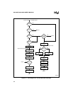
This microcontroller’s flexible interrupt-handling system has two main components: the pro-
grammable interrupt controller and the peripheral transaction server (PTS). The programmable
interrupt controller has a hardware priority scheme that can be modified by your software. Inter-
rupts that go through the interrupt controller are serviced by interrupt service routines that you
provide. The upper and lower interrupt vectors in special-purpose memory (see Chapter 5,
“Memory Partitions”) contain the lower 16 bits of the interrupt service routines’ addresses. The
CPU automatically adds FF0000H to the 16-bit vector in special-purpose memory to calculate the
address of the interrupt service routine, and then executes the routine. The peripheral transaction
server (PTS), a microcoded hardware interrupt processor, provides high-speed, low-overhead in-
terrupt handling; it does not modify the stack or the PSW. You can configure most interrupts (ex-
cept NMI, trap, and unimplemented opcode) to be serviced by the PTS instead of the interrupt
controller.
The PTS supports four special microcoded routines that enable it to complete specific tasks in
much less time than an equivalent interrupt service routine can. It can transfer bytes or words,
either individually or in blocks, between any memory locations in page 00H and can generate
pulse-width modulated (PWM) signals. PTS interrupts have a higher priority than standard inter-
rupts and may temporarily suspend interrupt service routines.
A block of data called the PTS control block (PTSCB) contains the specific details for each PTS
routine (see “Initializing the PTS Control Blocks” on page 6-17). When a PTS interrupt occurs,
the priority encoder selects the appropriate vector and fetches the PTS control block (PTSCB).


