8XC196NP, 80C196NU USER’S MANUAL
A-36
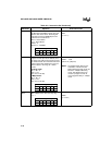
RST RESET SYSTEM. Initializes the PSW to zero,
the EPC/PC to FF2080H, and the pins and
SFRs to their reset values. Executing this
instruction causes the RESET# pin to be
pulled low for 16 state times.
SFR
← Reset Status
Pin
← Reset Status
PSW
← 0
EPC/PC
← FF2080H
RST
(11111111)
PSW Flag Settings
ZNCVVTST
000000
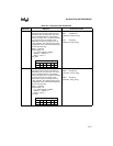
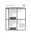
SCALL SHORT CALL. Pushes the contents of the
program counter (the return address) onto
the stack, then adds to the program counter
the offset between the end of this instruction
and the target label, effecting the call. The
offset must be in the range of –1024 to
+1023.
64-Kbyte mode:
SP
← SP – 2
(SP)
← PC
PC
←PC+11-bit disp
1-Mbyte mode:
SP
← SP – 4
(SP)
← PC
PC
←PC+11-bit disp
SCALL cadd
(00101xxx) (disp-low)
NOTE: The displacement (disp) is sign-
extended to 16-bits in the 64-
Kbyte addressing mode and to 24
bits in the 1-Mbyte addressing
mode. This displacement may
cause the program counter to
cross a page boundary in 1-Mbyte
mode.
PSW Flag Settings
ZNCVVTST
——————
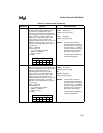
SETC SET CARRY FLAG. Sets the carry flag.
C
← 1SETC
(11111001)
PSW Flag Settings
ZNCVVTST
—— 1 ———
Table A-6. Instruction Set (Continued)
Mnemonic Operation Instruction Format


