8XC196NP, 80C196NU USER’S MANUAL
13-36
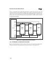
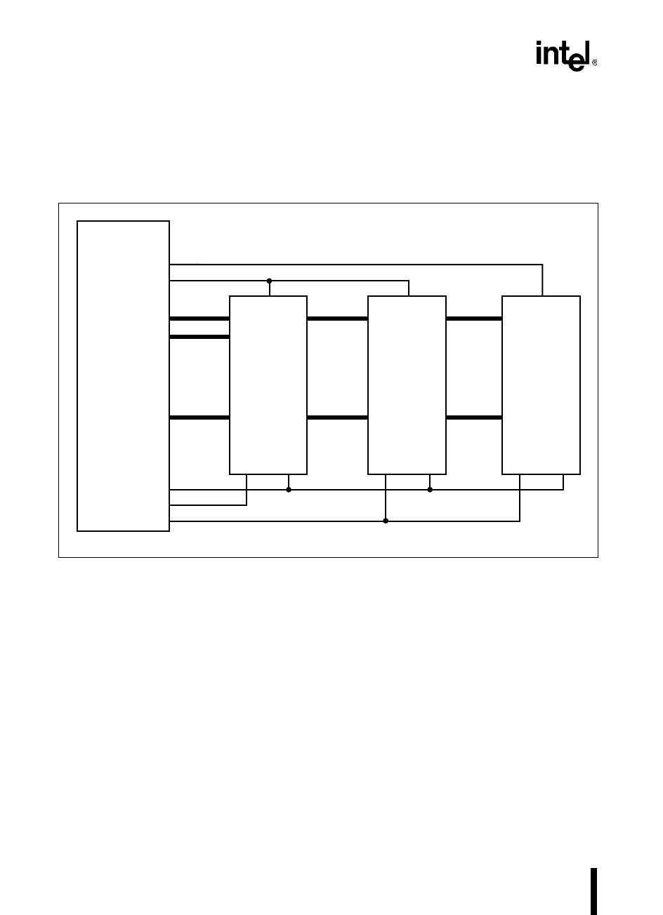
Figure 13-19 illustrates the use of the write strobe mode in a mixed 8-bit and 16-bit system with
two flash memories and one SRAM. The WRL# signal, which is generated for all 8-bit writes
(Table 13-14), is used to write bytes to the SRAM. Note that the RD# signal is sufficient for sin-
gle-byte reads on a 16-bit bus. Both bytes are put onto the data bus and the memory controller
discards the unwanted byte.
Figure 13-19. A System with 8-bit and 16-bit Buses
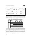
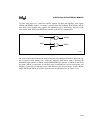
13.9 SYSTEM BUS AC TIMING SPECIFICATIONS
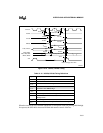
Refer to the latest datasheet for the AC timings to make sure your system meets specifications.
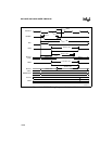
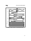
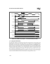
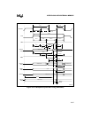
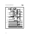
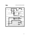
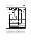
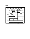
The major external bus timing specifications are shown in Figure 13-20 through 13-23.
CS1#
CS0#
AD15:8
AD7:0
RD#
WRH#
8XC196
Flash
256K×8
High
CE#
A17:0
D7:0
A17:0
D7:0
CE#
OE#WE# OE#WE#
A18:1 A18:1
AD7:0
A2439-03
Flash
256K×8
Low
A12:0
D7:0
CE#
OE#WE#
A12:0
AD7:0
SRAM
8K×8
WRL#
A19:0
AD15:8


