9-8
8XC196NP, 80C196NU USER’S MANUAL
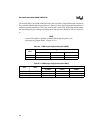
Pulsewidth (in µs) =
Duty Cycle (in %) =
where:
PWM
x
_CON = 8-bit value to load into the PWM
x
_CONTROL register
Pulsewidth = width of each high pulse
f = operating frequency, in MHz
T
PWM
= output period on the PWM pin, in µs
†
80C196NU only.
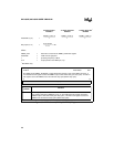
Clock Prescaler
Disabled
÷2 Clock Prescaler
Enabled
÷4 Clock Prescaler
†
Enabled
PWM
x
_CONTROL
x
= 0–2
Address:
Reset State:
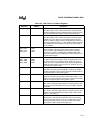
Table 9-2
00H
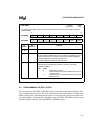
The PWM control (PWM
x
_CONTROL) register determines the duty cycle of the PWM
x
channel. A
zero loaded into this register causes the PWM to output a low continuously (0% duty cycle). An FFH in
this register causes the PWM to have its maximum duty cycle (99.6% duty cycle).
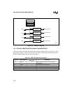
7 0
PWM Duty Cycle
Bit
Number
Function
7:0 PWM Duty Cycle
This register controls the PWM duty cycle. A zero loaded into this register causes the
PWM to output a low continuously (0% duty cycle). An FFH in this register causes the
PWM to have its maximum duty cycle (99.6% duty cycle).
Figure 9-5. PWM Control (PWM
x
_CONTROL) Register
PWM
x
_CON 2×
f
-----------------------------------------------
PWM
x
_CON 4×
f
-----------------------------------------------
PWM
x
_CON 8×
f
-----------------------------------------------
Pulsewidth
T
PWM
---------------------------------
100×


