7-17
I/O PORTS
7.3.2 Configuring EPORT Pins
Each EPORT pin can be individually configured to operate either as an extended-address signal
or as an I/O pin in one of these modes:
• complementary output (output only)
• high-impedance input or open-drain output (input, output, or bidirectional)
7.3.2.1 Configuring EPORT Pins for Extended-address Functions
The EPORT pins default to their extended-address functions upon reset (see Table B-5 on page
B-13). During program execution, the pins can be reconfigured at any time from address to I/O
and back to address. However, this is not recommended unless you understand the implications
of changing memory addressing “on the fly.” To change a pin from I/O to address, clear the
EP_REG.x bit and set the EP_MODE.x bit. (Clearing EP_REG.x is required for compatibility
with software development tools.)
7.3.2.2 Configuring EPORT Pins for I/O
To configure a pin for I/O, write the appropriate values to the control registers, in this order:
1. EP_DIR
2. EP_MODE
3. EP_REG
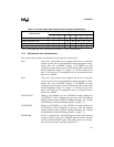
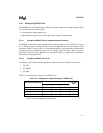
Table 7-13 lists the register settings for the EPORT pins.
Table 7-13. Configuration Register Settings for EPORT Pins
Desired Pin Configuration
Configuration Register Settings
EP_PIN
Value
EP_DIR EP_MODE EP_REG
Address X
†
10
††
address
Complementary output 0 0 data value data value
Open-drain output 1 0 data value data value
Input 1 0 1 I/O pin value
†
X = Don’t care.
††
Must be zero for compatibility with software tools.


