12-10
8XC196NP, 80C196NU USER’S MANUAL
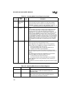
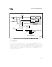
During normal operation (before entering powerdown mode), an internal pull-up holds the
RPD pin at V
CC
. When an external interrupt signal is asserted, the internal oscillator circuitry is
enabled and turns on a weak internal pull-down. The resistance of the internal pull-down should
be approximately 10 kΩ. This weak pull-down causes the external capacitor (C
1
) to begin dis-
charging at a typical rate of 200 µA. When the RPD pin voltage drops below the threshold voltage
(about 2.5 V for 5 V operation and 1.6 V for 3 V operation), the internal phase clocks are enabled
and the device resumes code execution.
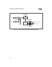
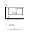
At this time, a Schmitt-triggered detection circuit prompted by the switching voltage levels
strongly drives a logic one, quickly pulling the RPD pin back up to V
CC
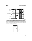
(see recovery time in Fig-
ure 12-5). The time constant (RC) follows an exponential charging curve. However, since there
is no external resistor on the RPD pin, the time constant goes to zero and the recovery time is
instantaneous.
where:
V
C
= Charging capacitor voltage
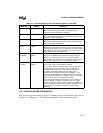
12.5.3.3 Selecting C
1
With the resistance of the discharge path designed into the silicon via the internal pull-down, the
selection of an external capacitor (C
1
) can be critical. Ideally, you want to select a component that
will produce a sufficient discharge time to permit the internal oscillator circuitry to stabilize. Be-
cause many factors can influence the discharge time requirement, you should always fully char-
acterize your design under worst-case conditions to verify proper operation.
V
c
V
cc
1e
tτ⁄()
] τ RC
1
0==();–[=
V
c
V
cc
=


