Reference Manual
00809-0100-4808, Rev CA
June 2008
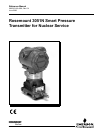
Rosemount 3051N
www.rosemountnuclear.com
Table of Contents
SECTION 1
Introduction
Using This Manual. . . . . . . . . . . . . . . . . . . . . . . . . . . . . . . . . . . . . . . . 1-1
SECTION 2
Transmitter Functions
Overview . . . . . . . . . . . . . . . . . . . . . . . . . . . . . . . . . . . . . . . . . . . . . . . 2-1
Safety Messages . . . . . . . . . . . . . . . . . . . . . . . . . . . . . . . . . . . . . . . . . 2-1
Warnings . . . . . . . . . . . . . . . . . . . . . . . . . . . . . . . . . . . . . . . . . . . . 2-1
Failure Mode Alarm . . . . . . . . . . . . . . . . . . . . . . . . . . . . . . . . . . . . . . . 2-2
Alarm Level Verification . . . . . . . . . . . . . . . . . . . . . . . . . . . . . . . . . 2-2
Transmitter Security. . . . . . . . . . . . . . . . . . . . . . . . . . . . . . . . . . . . . . . 2-2
Security Jumper (Write Protect) . . . . . . . . . . . . . . . . . . . . . . . . . . . 2-3
Local Zero and Span (Local Keys) Software Lock Out. . . . . . . . . . 2-3
Physical Removal of Local Zero and Span (Local Keys) . . . . . . . . 2-3
Configuring Transmitter Alarm
and Security Jumper Procedure . . . . . . . . . . . . . . . . . . . . . . . . . . . . . 2-3
Commissioning the Rosemount 3051N with a
HART-Based Communicator . . . . . . . . . . . . . . . . . . . . . . . . . . . . . . . . 2-4
Setting the Loop to Manual. . . . . . . . . . . . . . . . . . . . . . . . . . . . . . . 2-5
Wiring Diagrams (Bench Hook-up). . . . . . . . . . . . . . . . . . . . . . . . . 2-5
Wiring Diagrams (Field Hook-up) . . . . . . . . . . . . . . . . . . . . . . . . . . 2-6
Review Configuration Data . . . . . . . . . . . . . . . . . . . . . . . . . . . . . . . . . 2-7
Check Output. . . . . . . . . . . . . . . . . . . . . . . . . . . . . . . . . . . . . . . . . . . . 2-7
Process Variables. . . . . . . . . . . . . . . . . . . . . . . . . . . . . . . . . . . . . . 2-7
Sensor Temperature. . . . . . . . . . . . . . . . . . . . . . . . . . . . . . . . . . . . 2-8
Basic Setup . . . . . . . . . . . . . . . . . . . . . . . . . . . . . . . . . . . . . . . . . . . . . 2-8
Set Process Variable Units. . . . . . . . . . . . . . . . . . . . . . . . . . . . . . . 2-8
Set Output . . . . . . . . . . . . . . . . . . . . . . . . . . . . . . . . . . . . . . . . . . . 2-8
Rerange . . . . . . . . . . . . . . . . . . . . . . . . . . . . . . . . . . . . . . . . . . . . . 2-9
Rerange with a Communicator Only. . . . . . . . . . . . . . . . . . . . . . . . 2-9
Rerange with a Pressure Input Source and a Communicator . . . 2-10
Rerange with a Pressure Input Source and
the Local Zero and Span Buttons. . . . . . . . . . . . . . . . . . . . . . . . . 2-10
Damping . . . . . . . . . . . . . . . . . . . . . . . . . . . . . . . . . . . . . . . . . . . . 2-12
LCD Meter Options. . . . . . . . . . . . . . . . . . . . . . . . . . . . . . . . . . . . 2-12
Detailed Setup . . . . . . . . . . . . . . . . . . . . . . . . . . . . . . . . . . . . . . . . . . 2-12
Local Span and Zero Control (Local Keys). . . . . . . . . . . . . . . . . . 2-12
Sensor Temperature Output Unit Selection . . . . . . . . . . . . . . . . . 2-12
Diagnostics and Service . . . . . . . . . . . . . . . . . . . . . . . . . . . . . . . . . . 2-12
Transmitter Test . . . . . . . . . . . . . . . . . . . . . . . . . . . . . . . . . . . . . . 2-13
Loop Test . . . . . . . . . . . . . . . . . . . . . . . . . . . . . . . . . . . . . . . . . . . 2-13
Calibration . . . . . . . . . . . . . . . . . . . . . . . . . . . . . . . . . . . . . . . . . . . . . 2-13
Calibration Overview . . . . . . . . . . . . . . . . . . . . . . . . . . . . . . . . . . 2-15
Deciding Which Trim Procedure to Use . . . . . . . . . . . . . . . . . . . . 2-16
Sensor Trim . . . . . . . . . . . . . . . . . . . . . . . . . . . . . . . . . . . . . . . . . 2-16


