


Reference Manual
00809-0100-4808, Rev CA
June 2008
3-13
Rosemount 3051N
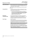
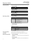
FIGURE 3-7. Power Supply
Load Limitations.
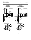
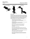
Wiring To make connections, perform the following procedure:
1. Remove the housing cover on the side marked “FIELD TERMINALS.” Do
not remove the cover in explosive atmospheres when the circuit is alive.
All power to the transmitter is supplied over the signal wiring.
2. Connect the lead that originates at the positive side of the power supply
to the terminal marked “+” and the lead that originates from the negative
side of the power supply to the terminal marked “–”. Avoid contact with
the leads and terminals. Do not connect the powered signal wiring to the
test terminals. Power could damage the test diode in the test connection.
3. Plug and seal unused conduit connections on the transmitter housing to
avoid moisture accumulation in the terminal side of the housing. If you do
not seal the unused connections, mount the transmitter with the electrical
housing positioned downward for drainage. Install wiring with a drip loop.
Arrange the drip loop so the bottom is lower than the conduit connections
and the transmitter housing.
NOTE
Signal wiring needs to be shielded, but use twisted pairs for best results. In
order to ensure proper communication, use 24 AWG or larger wire, and do not
exceed 5000 feet (1 500 meters).
Do not use inductive-based transient protectors, including the Rosemount
470, as they can adversely affect the output of Rosemount 3051N 4–20 mA
transmitters.The Rosemount 3051N includes the transient protection terminal
block (T1) as standard.
Signal Wiring Grounding
Do not run signal wiring in conduit or open trays with power wiring, or near
heavy electrical equipment. You may ground the signal wiring at any one point
on the signal loop, or leave it ungrounded. The negative terminal of the power
supply is a recommended grounding point.
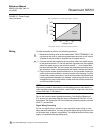
Communication requires a minimum loop resistance of 250 ohms.
Max. Loop Resistance = 43.5 (Power Supply Voltage – 10.5) ohms
0
500
1000
1500
1935
10.5 20
30
40 55
Load (ohms)
Voltage (V dc)
Design
Region
See “Safety Messages” on page 3-1 for warning information.