


Reference Manual
00809-0100-4808, Rev CA
June 2008
2-3
Rosemount 3051N
1. Security Jumper: prevents all writes to transmitter configuration.
2. Local Keys (Local Zero and Span) Software Lock Out: prevents
changes to transmitter range points via local zero and span
adjustment keys. With local keys security enabled, changes to
configuration are possible via HART.
3. Physical Removal of Local Keys (Local Zero and Span) Magnetic
Buttons: removes ability to use local keys to make transmitter range
point adjustments. With local keys security enabled, changes to
configuration are possible via HART.
NOTE
If the security jumper is not installed, the transmitter will continue to operate in
the security OFF configuration.
Security Jumper
(Write Protect)
You can prevent changes to the transmitter configuration data with the write
protection jumper. Security is controlled by the security (write protect) jumper
located on the electronics board or meter face. Position the jumper on the
transmitter circuit board in the “ON” position to prevent accidental or
deliberate change of configuration data.
If the transmitter write protection jumper is in the “ON” position, the transmitter
will not accept any “writes” to its memory. Configuration changes, such as
digital trim and reranging, cannot take place when the transmitter security is
on.
Local Zero and Span
(Local Keys) Software
Lock Out
To enable this feature, see “Local Span and Zero Control (Local Keys)” in
Section 2.
Physical Removal of
Local Zero and Span
(Local Keys)
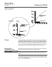
To remove the magnetic buttons used to activate the local zero and span, use
a small slotted head screwdriver and pry off the small, plastic cap located
under the approval tag. Remove button assemblies and discard.
CONFIGURING
TRANSMITTER ALARM
AND SECURITY JUMPER
PROCEDURE
To reposition the jumpers, follow the procedure described below.
1. If the transmitter is installed, secure the loop and remove power.
2. Remove the housing cover opposite the field terminal side. Do not
remove the transmitter covers in explosive atmospheres when the
circuit is alive.
3. Reposition the jumpers as desired.
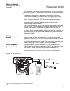
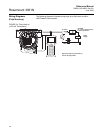
• Figure 2-1 shows the jumper positions for Electronics Boards.
• Figure 2-2 shows transmitters with an optional LCD meter.
4. Reattach the transmitter cover. Transmitter covers must be fully
engaged to meet explosionproof requirements.